3DPrinting

15881 readers
613 users here now

3DPrinting is a place where makers of all skill levels and walks of life can learn about and discuss 3D printing and development of 3D printed parts and devices.

The r/functionalprint community is now located at: or [email protected]

There are CAD communities available at: [email protected] or [email protected]

Rules

If you need an easy way to host pictures, https://catbox.moe may be an option. Be ethical about what you post and donate if you are able or use this a lot. It is just an individual hosting content, not a company. The image embedding syntax for Lemmy is ![](URL)

Moderation policy: Light, mostly invisible
founded 2 years ago
MODERATORS
51


I designed a part that has compartments for small neodymium magnets. The compartments open up on the side of the part, but ideally the entire part should look smooth and featureless, and the epoxy I use is not the same color as the PLA. Also, I'd like to be able to fish out the magnets later, and epoxy is a bit too final for my taste.

So I'm thinking of dropping a small dollop of melted PLA into the openings to seal them, then file / polish them smooth. It would be sticky enough to hold the magnets in place yet easy to pop off with something pointy or sharp if need be.

And to do that cleanly, I figured I'd get me one of those cheap freehand 3D pens as a kind of precision "glue gun" for PLA. And it occurs to me that I might also be able to use it to "weld" small parts together, and hand-write things on parts with a different color filament.

I'm not much of an artist so I have no use for a 3D pen as an artsy tool. But it seems like a useful thing to have alongside a 3D printer, and they're not that expensive - even the more expensive Mynt3D 3D Pen Pro, which is the one I'm eyeing.

Does anybody know if those 3D pens can be used for small manual reworks / assembly of PLA parts?

52


Like the Ender 3 V3 SE at $200 and the Ender 3 S1 Pro at $250.

They don't seem to have any interesting deals on consumables, sadly.

53
118
Acetone is your friend (lemmy.sdf.org)
submitted 1 month ago* (last edited 1 month ago) by [email protected] to c/3dprinting


You might recall that I tried printing this fake lens last week and found it quite challenging.

So today for S&G, I figured I'd try to print it in two halves like so:

Sliced lens halves

Then instead of gluing or epoxying them, I joined them with acetone: it's quite a thin profile, so it's a good test of the strength of the bond.

Well, I let it cure for half an hour just to make sure all the acetone inside the bond had evaporated, and it certainly is plenty strong! Strong enough to take a vigorous chemical polishing - with acetone also - while applying a fair amount of pressure and stay in one piece.

I polished it by hand for 5 minutes and it's even a bit lens-y now 🙂

I'll let it cure for another 24 hours for good measure, then tomorrow I'll mount it in the lathe and I'll polish it some more with acetone, to see how clear I can make it.

It's never going to be any good of course, but it's interesting to see how much it can be improved, if only to find out what I can do with PLA.

54
15
Weird extrusions (self.3dprinting)
submitted 1 month ago* (last edited 1 month ago) by lukstru to c/3dprinting


I just stopped a failing print and noticed some weird extrusions happening (not english native speaker, also I'm a 3d printing noob, don't know whether that's the right word). You can see it in the image. Any tips to improve printing quality?

I'm printing on an Ender 3 V3 SE. This print was with standard settings.

EDIT: as a clarification, this isn't why I stopped the print. It failed to adhere to the print plate at some spots. Redid my z offset and hopefully that solved it.

55
23
submitted 1 month ago by seasick to c/3dprinting


Like every year I am absolutely clueless what to gift my loved ones (and of course always too late getting/creating them).

Thats why I'm asking you guys, for inspiration - what, if any, are you printing this year as gifts for your loved ones?

56


I'm currently using an Orbiter 1.5 and it's pretty decent but I'm looking for an upgrade. I like the light style extruder sitting on the gantry over a Bowden system as it allows for flexible filament and has much better control over retraction.

Is the 2.0 a significant improvement over the 1.5? Should I get a new hotend as well with it?

Right now I'm using a MicroSwiss all metal hotend and am quite satisfied with it.

Print speed is okay I guess.

57


How is the build chamber in your 3D-printer heated? Is there any thermal insulation and if how thick is it?

My two cents:

** thermal insulation**

That's the math for a small 300x300mm printer heated to 70°C (for 130°C tripple this number).

With a 6030 aluminium extrusion a 60mm insulation would fit within the walls and bring down the heatloss to approx. 45W. In other words: Once it is heated up the thermal losses are small enough for it to hold the temperature on its own. Reducing the overall power consumption.

heating/temperature control

For cooling and heating: oil<-> air heat exchanger/radiator might be a good solution:

  • place one inside the printer
  • the other on the outside
  • insert a heater in the loop (only when heating is required, for cooling keep it off)
  • possible to push past the 100°C liquid temperature.

Add a fan that circulates the air within the chamber to equalize the temperature.

This way the chamber can be heated and cooled without venting any air into the room.

58
11
submitted 1 month ago* (last edited 1 month ago) by [email protected] to c/3dprinting


I have some very consistent issues with warping when printing ASA/ABS, which is really annoying since I'm trying to print my voron parts. It's not warping massively, but enough to mess things up.

I print with these general settings, on a textured PEI flex-plate.

  • heated chamber @ 45-47C (can't go much higher)
  • bed temp @105C
  • first layer 255C, other layers 245C
  • fan off, unless it's an overhang >=50% or layer time is <10s. Fan maxes out @70% unless bridging.
  • speed 200/120 mm/s inner/outer walls
  • first layer 50mm/s, 80mm/s infill

I've tried both with my regular Z-offset which creates a good uniform first layer, and slightly lower to kind of push it more on to the plate (but worse looking)

  • I've cleaned the plate with pure IPA
  • I've tried glue stick
  • I've tried brim both skirts/mouse ears, which help but don't eliminate it. (5mm, 0.15mm space)

ABS seems to be a little easier to print than the ASA. I'm using filament from Polymaker

59


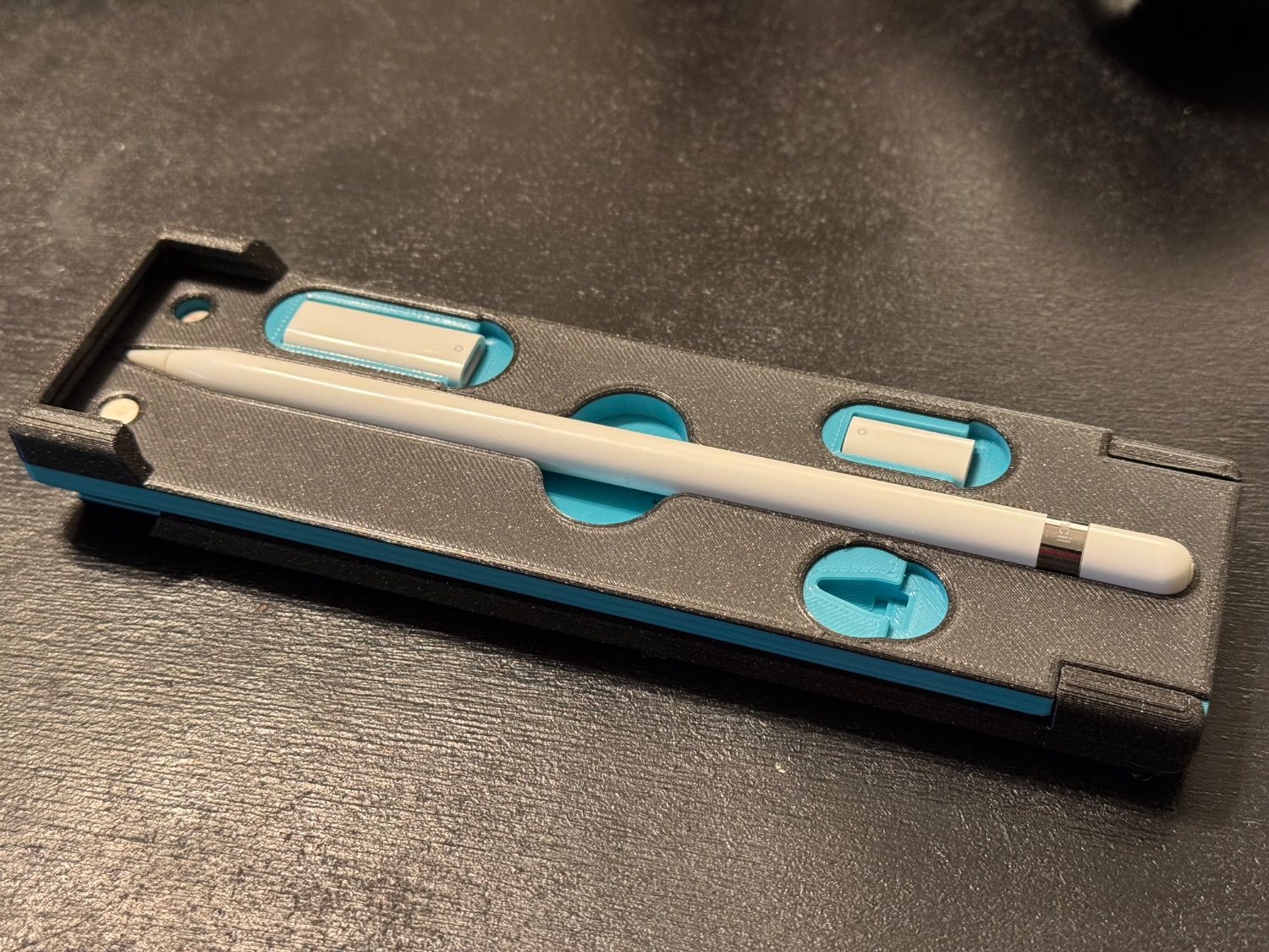
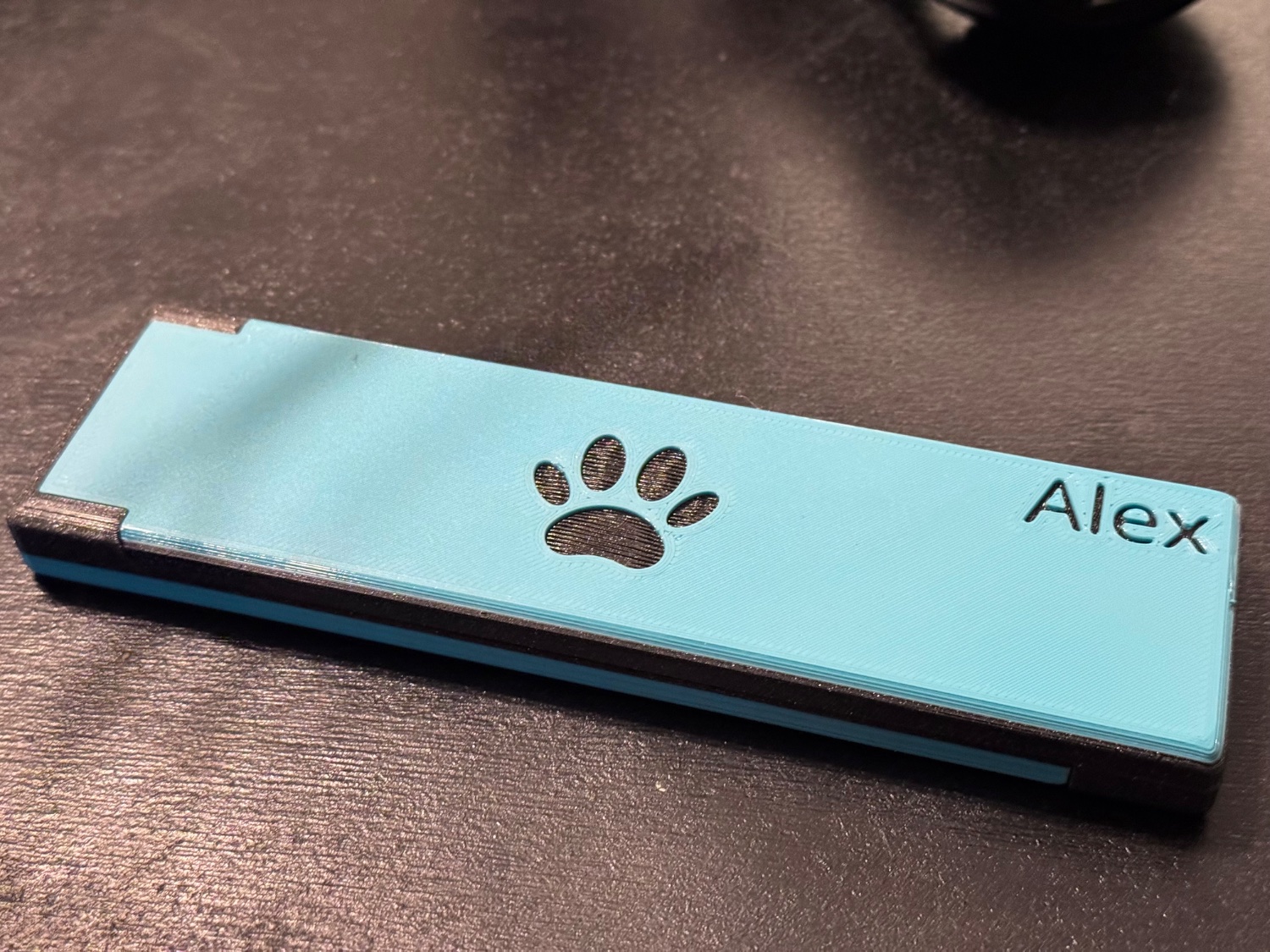
It’s a slight modification to my existing design which can be found here: https://www.printables.com/model/261466-apple-pencil-gen-1-case-mkii

The two tone was originally created by accident as we were running out of light blue and I decided to go all out on the top side.

She is very happy with the results.

60
291
submitted 1 month ago* (last edited 1 month ago) by seasick to c/3dprinting


See https://imgur.com/a/zMvfpRc for more pics

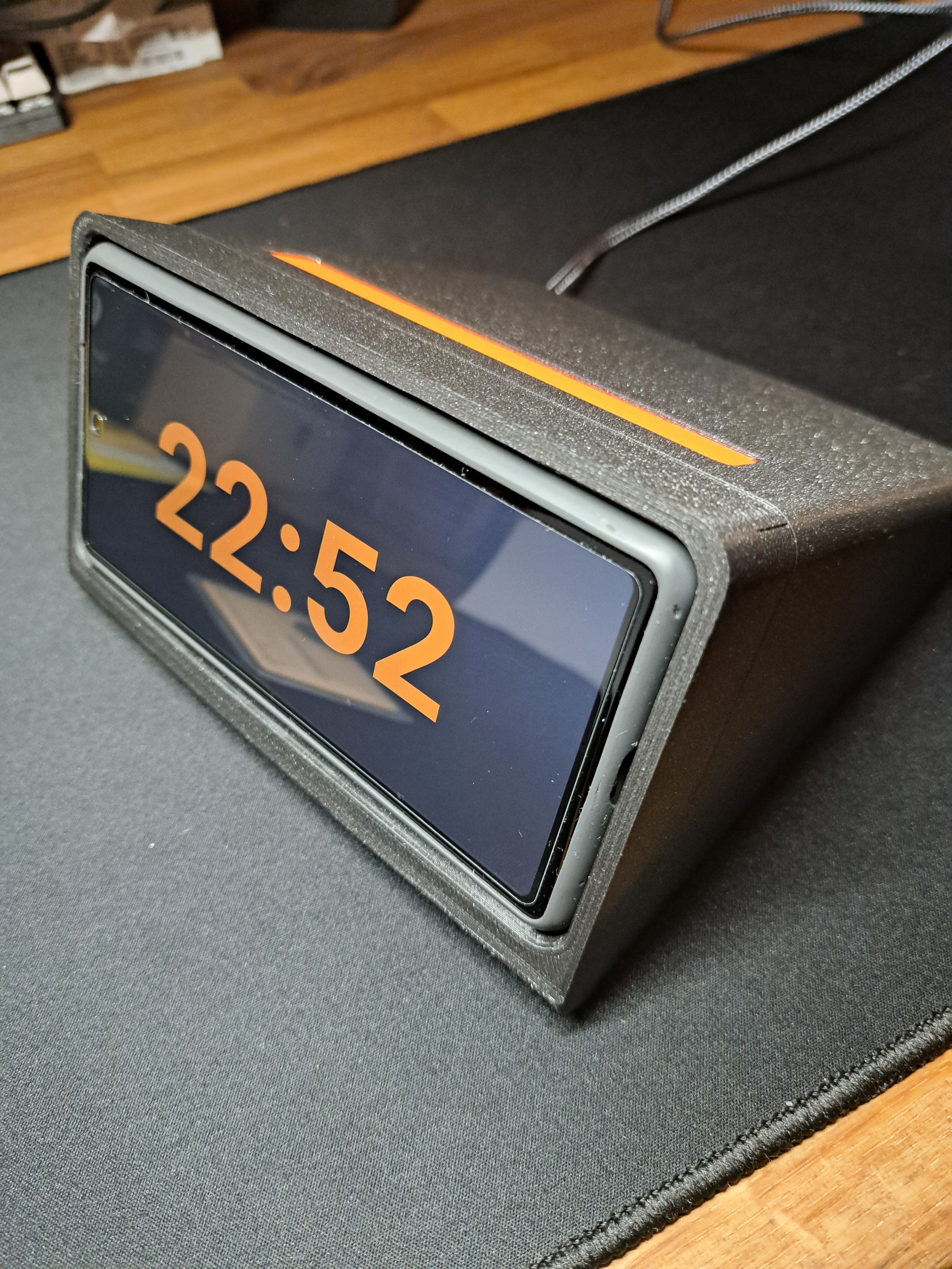
A few months ago, Scott Yu showcased a phone dock inspired by Dieter Rams' iconic DN40 digital clock.

That got me inspired to create my own version, featuring a wireless charger from IKEA. The charger is integrated into a panel that slides into a slot within the dock's body. Before assembling, the cable is routed through a hole in the back for a clean and functional setup.

Printed with Prusament PLA Galaxy Black & Prusament PETG Orange.

To top it off, I even developed my own Android docking app — because, why not? :D

61
51
submitted 1 month ago* (last edited 1 month ago) by [email protected] to c/3dprinting


I have a cheap bedslinger, an Anycubic Kobra 2, and generally it's a pretty decent printer at the price. I have flashed klipper FW on it, so I'm not using Anycubics FW.

I have issues whenever I try printing bigger parts, the first layer is always complete shit (see post photo).

Heightmap, measured with inductive probe heightmap range is only 0.085mm from min to max, so it should be reasonably flat. The heightmap is automatically recalibrated and loaded as part of my print_begin macro.

Slicer settings for line width slicer settings for layer widths

I don't know if my printer just doesn't correct Z-height during first layer, if my line width settings are completely messed up or what is causing this, but the issue is only apparent on bigger parts with large contract surface on the bed.

[SOLVED] It was just Z-offset that was too low causing this. however when running the calibration routine from ellis3dp on first layer squish, the settings that looked good on the small calibration patches, looked like crap on bigger prints. I needed a bit higher Z-offset, but that solved it.

62


This is a long video about printing and cleaning up FDM minis. Great video if you are hyper fixated on this topic. I'm doing a test print now, using his support profile and Fat Dragon's .08 profile for the A1 Mini. Tons of good information.

63


Bit of a weird question but how do you store and organize your models/STL files?

I do most of my CAD in OnShape these days so I have The Cloud for all the convenience and future horror of that. And... when I grab stuff from one of the sites like thingiverse... I SHOULD save the model but I don't and it has only bothered me once when I lost my webcam cover. And I probably spent more time searching for a replacement than it took to just make my own.

But I want to get more into kickstarters (... I feel dirty) and buying cool models and those I DO want to archive and save.

Most likely I'll just make a folder structure and sync it to my NAS with syncthing. But are there any better/more elaborate solutions? One of those "have server, will spin up container" things but figured I would ask first.

Thanks.

64


It occurred to me that one way to potentially eliminate all filament swap waste from purge towers or Bambu-style filament “poops” is to instead do something similar to a “purge object” or a “wipe object” but where the object is… filament.

The idea was somewhat inspired by Stefan’s video from a few months ago, which first introduced me to the idea of printing filament: https://m.youtube.com/watch?v=CQ-N1fr4N0w

If the purge object is new filament, then you don’t need to figure out what to use it for immediately; you can store the mixed-color filament for later use until you have a genuine need for a color-agnostic or structural object. No more piles of fidget spinners you didn’t really want.

A few other thoughts:

  • The filament probably needs a minimum bend radius so it can feed into an extruder without breaking. One option would be to print a circle or a rounded square / squircle type of shape toward the perimeter of the build volume (potentially multiple concentric ones, or spiralized shapes). Another option would be to print disconnected straight segments.
  • The filament doesn’t need to be printed flat. It could potentially spiral upwards (likely with supports). That could help avoid print head collisions for taller models (in which case you might not want the head to have to get back down to <1.75mm from the print bed). In the most general case, the filament could be printed at arbitrary angles, even vertically, and could start at some height above the build plate (potentially supported by the object itself, for example in an object where color changes don’t start at the very bottom). Maybe the angle could even be optimized to provide the best match between purge volume per layer and volume of new filament printed on each layer.
  • A good solution probably requires a good way to connect multiple segments of printed filament together
  • Mixing materials rather than just colors seems like a bad idea to me (e.g. soluble supports) but I’m going to mention it as a possibility anyway; you could conceive of something inspired by Stefan’s composite material and intelligently organize the different materials within your new filament.
  • You could potentially control the mixes / transition colors that go into your purge filament, or even choose multiple different new filaments for different color transitions. For example, you might have separate new filaments for red-green, green-blue, and blue-red transitions. Maybe you want it create particularly pretty new filament, or avoid particularly ugly combinations.

I don’t actually have a multi-color / multi-filament printer, and I don’t have time to experiment with this (even though the first prototype could be as trivial using a filament shape as the wipe object in PrusaSlicer). I’m mostly sharing this to establish prior art in case someone nefarious seeks to patent something similar in the future (which is also why I added some half-baked thoughts that might make other things become obvious to someone skilled in the art), though it’d be great if the idea is actually good and someone could implement it well. Or for all I know this does already exist.

Thanks for taking the time to read this! Feel free to repost/share/steal the idea if you like it.

65


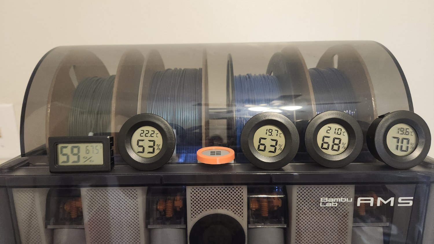
These have to be the least accurate things I have ever seen.

The rectangular one is accurate or accurate enough and has been what I used but I noticed files all had cutouts for these round hygrometers...

Well from my 6 pack 1 is within a margin of error to even be useful.

I get they aren't expensive but seems like a waste of money for this bad.

66


Back in college, I had a few classes on CAD (mostly for engineering design), and I became decently proficient with CATIA, SolidWorks, and Autodesk Inventor. Now that I’m getting into 3D printing, I’m coming back to CAD and finding my skills pretty rusty.

I plan to use FreeCAD as my main tool. Could anyone please recommend some tutorials that I can complete that would give me a solid working knowledge of FreeCAD and help me brush up on CAD in general?

67


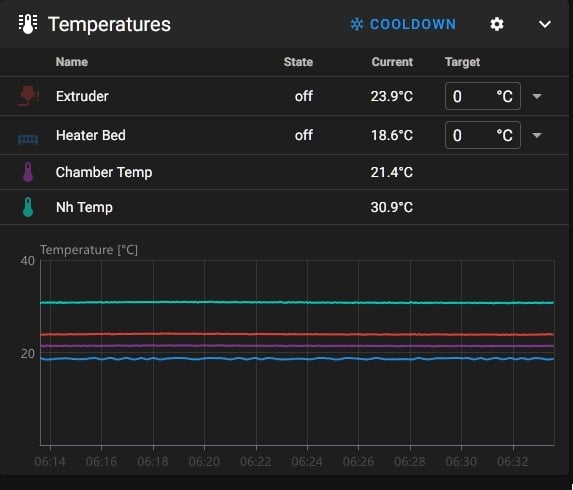
I am in the process of buttoning up a Nitehawk conversion on my Voron. I also replaced my extruder thermistor with an OE replacement purchased from a reputable vendor.

Post setup, my heated bed is reading spot on (it's 18.3 C in my basement aka 65 F). I verified that my extruder is also at ambient temperature by wedging a Thermapen under its silicone sock and letting it acclimate for 10 minutes. The I'm not sure why the extruder would be reading high.

I bought a spare thermistor and wired it in. The result was identical.

Thoughts? Ideas? I'm pretty sure I have the Nitehawk and thermistor set up correctly.

[extruder] step_pin: nhk:gpio23 dir_pin: nhk:gpio24
enable_pin: !nhk:gpio25
heater_pin: nhk:gpio9
sensor_pin: nhk:gpio29
pullup_resistor: 2200
sensor_type: ATC Semitec 104NT-4-R025H42G`

68


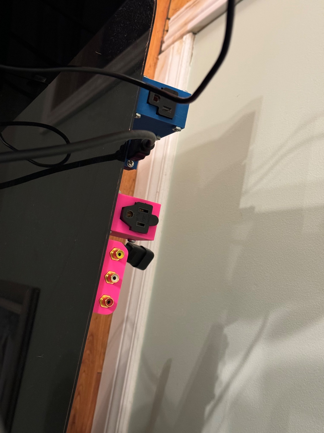
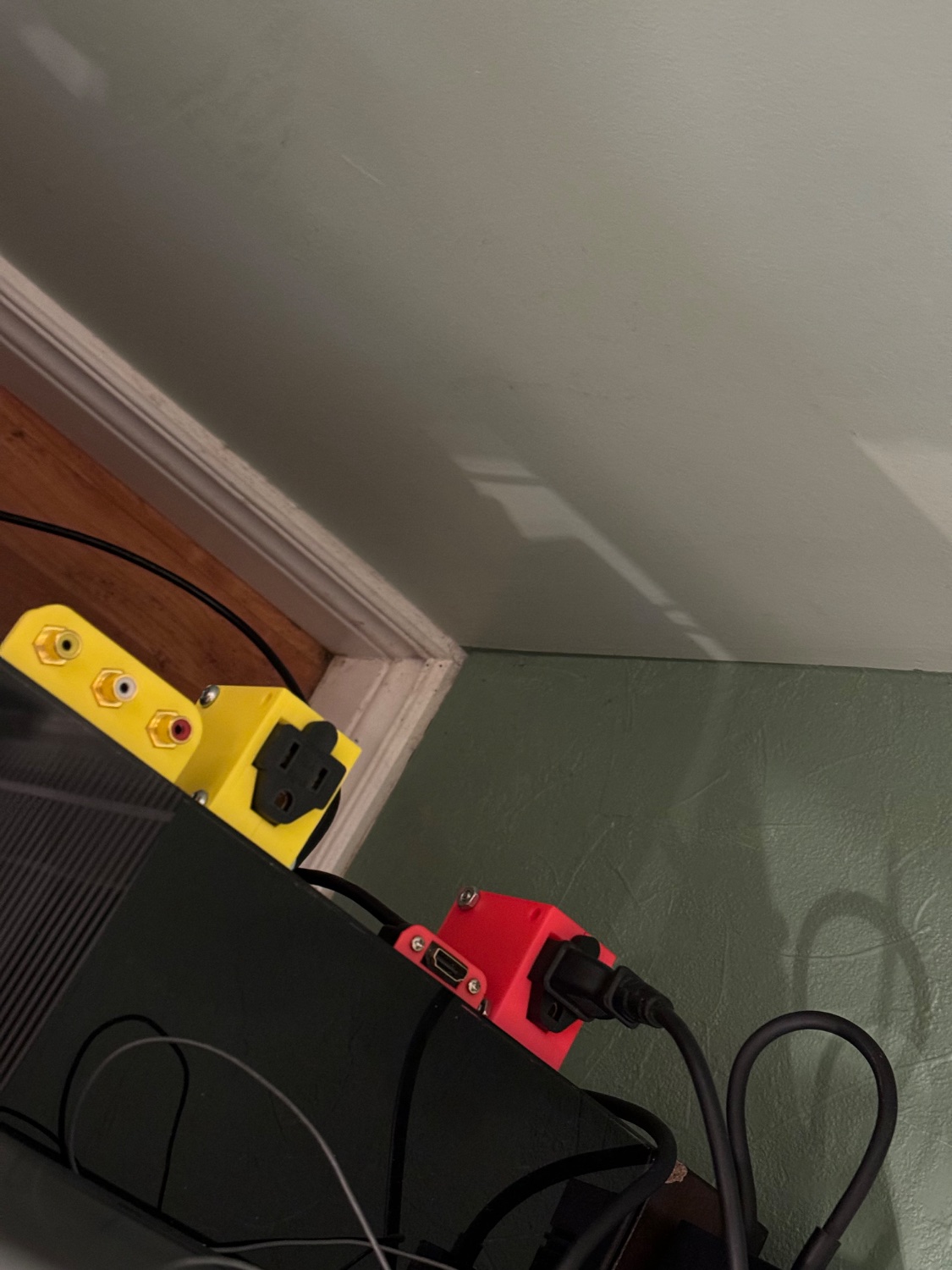
This is so that it’s easier to plugin old and new consoles without having to go on my hands and knees to Plug and unplug consoles.

69
147
FreeCAD v1.0 released. (blog.freecad.org)
submitted 1 month ago by wjrii to c/3dprinting


cross-posted from: https://lemmy.world/post/22260935

Let's take her out for a spin...

70


Sad to see them go this way, but not unexpected, thanks to the article by Josef Prusa where he complains about open source.

71
33
submitted 1 month ago* (last edited 1 month ago) by CommissarVulpin to c/3dprinting


Several years ago I leapt enthusiastically into the realm of 3D printing by buying a massive, expensive delta-type printer. I had to put it together myself, which was fun, but after that I struggled to get it to print well. Even simply trying to get the prints to stick to the bed were difficult, leading me to add huge brims to all my parts which were a pain to cut off afterward. Eventually I gave up fiddling with it and it’s been gathering dust ever since.

I know that a lot of you treat the hobby as an opportunity for endless tinkering and optimization, which is great, but I think I’ve realized that what I’d prefer is something that just works out of the box with a minimum of adjustment.

72
6
submitted 1 month ago* (last edited 1 month ago) by [email protected] to c/3dprinting


I found a small length of filament in the parts bin. I don't know what it is, and nobody else here does, or remembers ordering it. I'm pretty sure it's a sample that was sent by Prusa when we ordered the printer, and it's probably not a special material.

It's feels "gummy" and a lot softer than PLA, but not really rubbery either. And I tried printing something with it at 230C as if it was PLA and it's clearly not hot enough: it's able to flow out of the nozzle but it barely sticks to the bed.

Any idea what it could be?

73


In the process of refining the design for my 3D printed glasses (yes, I'm still at it 🙂) and trying to streamline the lens ordering process a bit, because some folks have told me their optician, or their optician's lens supplier, didn't really want to mess with "unusual" things like this, I decided to draw and print a fake ophthalmic lens. You know, not optical-quality - or even see-through - but something that looks and feels like a lens, that can be mounted in my frames, to show an optician hands-on how it works and that it's not weird or delicate to work on.

I figured it would be a quick print in clear PLA, that would require only a bit of cleanup and mount right into the frames, complete with the bevel and the notch and everything. How wrong I was...

This part is almost impossible to print right:

  • It's modeled after a real bispherical lens with an offset optical axis. I mean it's optically incorrect, but it has everything a real lens would have: uneven edge thickness, one convex and one concave side.

    You just can't set it flat on the bed in the slicer: none of it sits flat. The slicer has trouble generating support around the edge on the concave side that it interprets half of as overhang, and even if the beginning of the support doesn't get ripped off by the head and the print completes, the surfaces will be absolutely awful.

  • If you print it vertical - which frankly is the least bad option - then the bottom of the lens, under the support, will be a complete mess. The bevel won't even be visible. It takes quite some time to create supports that won't mess up the bottom of the lens too much

  • If you print it in clear PLA with only perimeters, it'll be transparent enough to see the spots were the perimeters are started at the next layer. And depending on your wall generation strategy, the spots where the printer tries to fill the voids will show up as round "halos" inside the lens.

    The lens' thickness varies everywhere, so the slicer tries its best to fill each layer, but it's slightly different at every layer. At any rate, it reveals the slicer's idiosyncracies in tool path stragegy right away.

  • The bevel all around the lens is only 0.5mm high. If the printer is dialed in, the bevel will show as an actual 120-degree bevel near the front face of the lens, particular where the bevel is normal to the layer, about half-way up the lens if you print it vertically. If not, it will look like a barely-raised blob.

I've tried this print on 3 different printer and I just can't get a decent print. All I can do is play with the settings in the slicer until it comes out not too terrible.

So, that part is a bit frustrating for my original purpose, but it turns out to be a great part to test a printer and/or the slicer software! If you want to try it too, it's here:

https://github.com/Giraut/3D-printed_eyeglasses/raw/refs/heads/main/lens_example.3mf

74


Which is to say, not very far on this at all but I think I have a good idea on how have my cake and eat it too for desiccant for my spools.

I am finding I can't get the humidity below about 50% in my AMS and the silica I am using needs constant refreshing.

Well it seems there is stuff called activated alumina that is pretty good and honestly about the same costs as silica beads, but I need to be able to put it in the oven to refresh it. Which doesn't work well with my 3d printed desiccant holders.

Insert, cheap tea strainers.
It seems I can get ones that are 4cm in width by 6cm in height that are made out of stainless steel that I can actually put straight in the oven.

So, I am working on getting the parts and items but was wondering if anyone else has done this or have any suggestions before I start grabbing stuff?

75
81
submitted 1 month ago by 4lan to c/3dprinting


My buddy has a cold plunge and this filter started cracking. After looking at it you can tell it's definitely 3d printed (and well)

On the left you can see my first attempt. I just cut rectangular holes in CAD and it's pretty close but not pretty. Printed in PETG on a K1 Max

Is there a way to do this in the slicer instead? I played around with 0 walls and different infill types but that didn't work out

view more: ‹ prev next ›