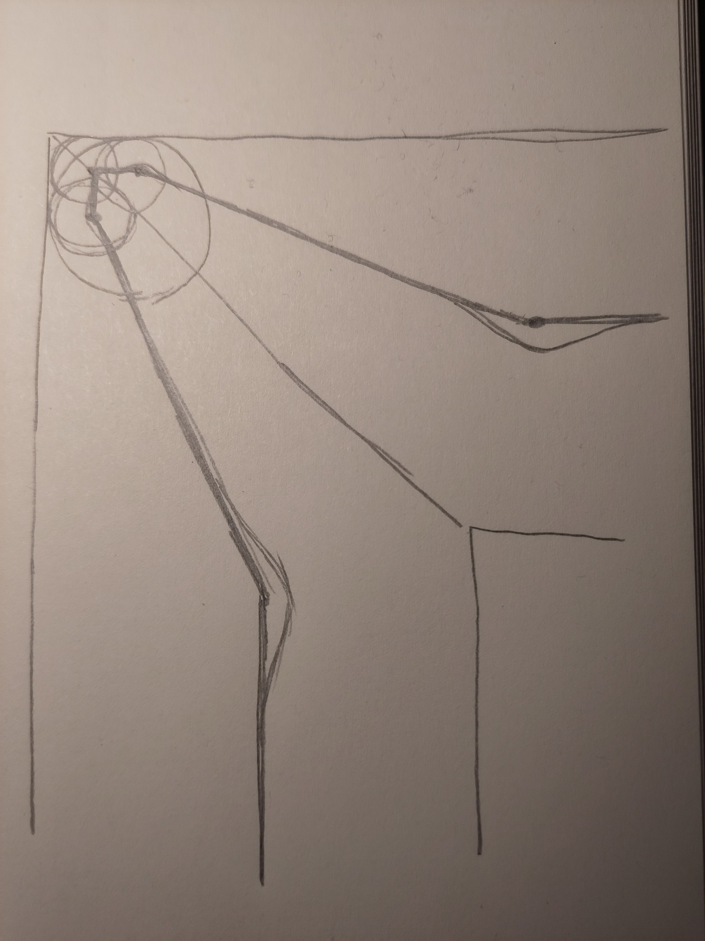
That looks cool in 2D, but do it in 3D and you'll see the issue - your corner will be lower than the rest of the wall.
3DPrinting
3DPrinting is a place where makers of all skill levels and walks of life can learn about and discuss 3D printing and development of 3D printed parts and devices.
The r/functionalprint community is now located at: or [email protected]
There are CAD communities available at: [email protected] or [email protected]
Rules
-
No bigotry - including racism, sexism, ableism, homophobia, transphobia, or xenophobia. Code of Conduct.
-
Be respectful, especially when disagreeing. Everyone should feel welcome here.
-
No porn (NSFW prints are acceptable but must be marked NSFW)
-
No Ads / Spamming / Guerrilla Marketing
-
Do not create links to reddit
-
If you see an issue please flag it
-
No guns
-
No injury gore posts
If you need an easy way to host pictures, https://catbox.moe may be an option. Be ethical about what you post and donate if you are able or use this a lot. It is just an individual hosting content, not a company. The image embedding syntax for Lemmy is 
Moderation policy: Light, mostly invisible
Why lower if you print everything at the same layer height?
Filament is not squeezed as a 2D dot, it's squeezed as a 3D sphere. If you decrease its radius, it will physically decrease in all three dimensions, not just two.
Why would that be? There is no physical rule saying that narrow extrusions need to be flatter as well.
Because the same squeezing effect shown in the 2d plane would occur on the 3d plane as well.
Hmm, not exactly sure I get your argument. I imagine every extrusion to tip slightly to the outside of the curve since material is elongated on the outside and squeezed on the inside. The excess material would be pushed to the inside while the outside of the curve would sink. Is that what you mean?
in 3d space, your corner extrusion would suddenly be much thinner, so the choices for your filament would be to either droop to be supported by the previous layer or for the filament to sit underextruded in space if your part cooler is really up to the challenge.
Why would it suddenly be much thinner?
Because that's what happens when you reduce the amount of material being extruded in order to create much thinner lines in order to create sharper corners.
But the corners will have the same amount of material, since it is basically extruding 2 times on the same location during a corner.
Which is why the original corners have too much material.
At this point there is basically only one way of knowing :D. I'll generate some g-code and give it a go.
It's all a question of what exactly "much thinner" means, I expect to have some positive effect of the proposed method even when the minimum extrusion width is above the threshold where things become too thin.
Overall I expect the described method to make more sense with large nozzles and wide extrusions.
Thanks for explaining what you mean!
Use cylinders instead of spheres?
That will be very complicated.
Isn’t this exactly what Pressure Advance does?
To my understanding, pressure advance only compensates for non-linearities in the extrusion process. These non-linearities, if not taken into account would thin out the path at the beginning (missing pressure) and lead to an excess of material at the end (excess pressure buildup).
With perfect compensation of these non-linearities but no changes to the target line-width and path, the minimum achievable outer radius is equal to that of the extrusion width. I'm wondering if that minimum radius could not be reduced by progressively reducing the target extrusion width the closer you get to the corner. On top of that you would need to adjust the path towards the outside in order to keep the outer wall straight.
Edit: to my understanding, a classical corner will also result in a buildup of material inside, this can be explained by the nozzle orifice dwelling longer on the inside of the corner. This excess moves to the inside, creating a round corner on the inside as well.
My proposal would also combat this inner excess, thus giving overall sharper corners.
Exactly. And the PA tuning that Ellis has is great for tweaking it.
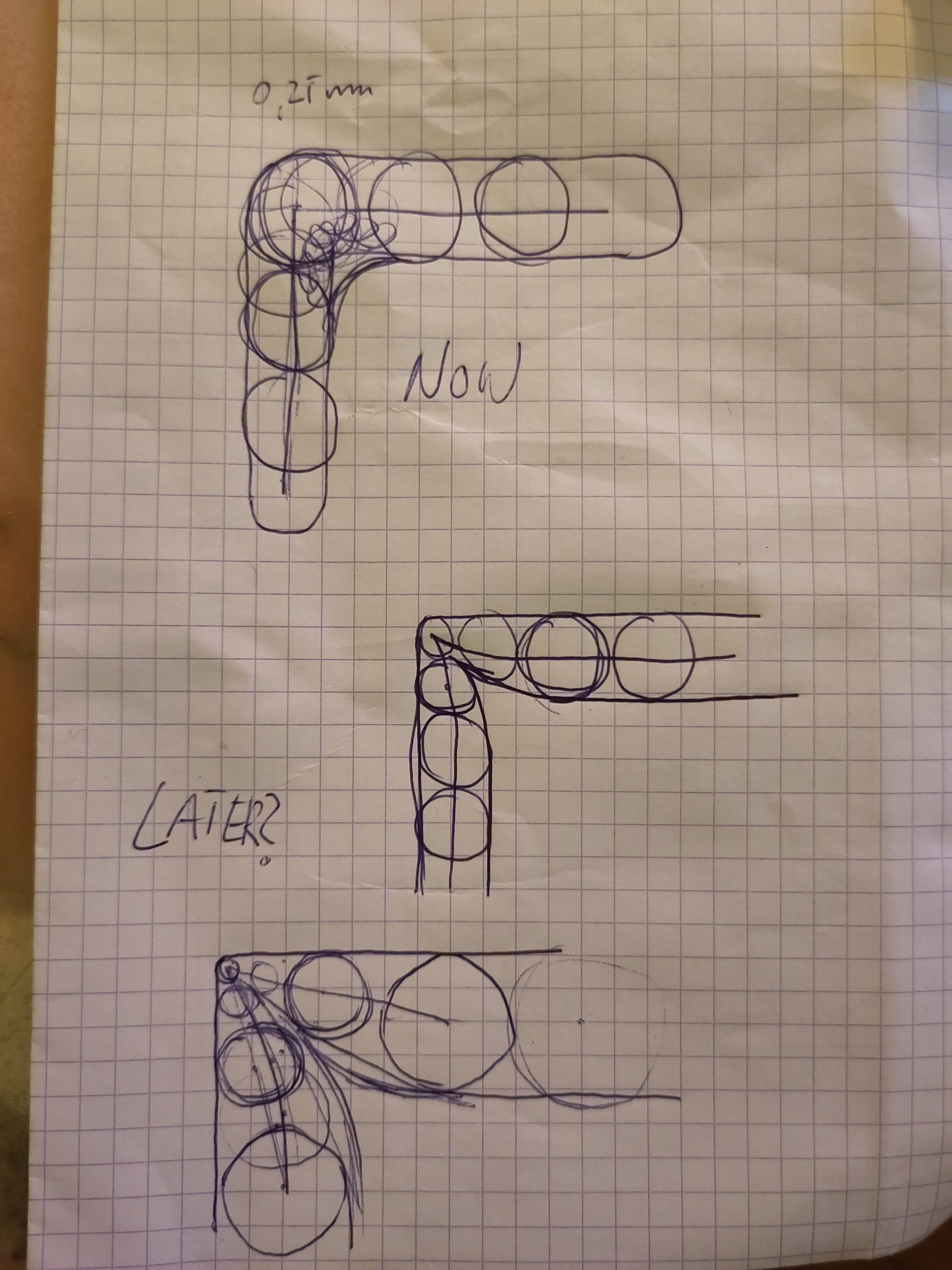
Maybe my sketch doesn't make it clear. I mean to intentionally make the extrusion narrower and make the print path go outwards to compensate for the narrower extrusion.
Pressure Advance does it. It reduces the extrusion at corners, accounts for coast speed, etc.
The actual extrusion or the extruder input? Of course it will also reduce the extrusion if badly tuned, I guess that's not the idea though. PA is also needed for straight lines with variable speed. It does help with corners but would need additional path corrections.
As shown in my sketches below:


Interesting. This is new to me and it looks like it could work. It could be usefull if you print with 0.6 nozzle at 0.6 mm width and then in a corner narrow it down to 0.4 mm
Exactly. Cura already does variable width lines but mostly to be able to print narrow sections or to fill narrow space between outlines. It could also use this technique to do sharper corners. Unfortunately to my understanding, firmwares don't yet support G1s with variable target extrusion rates. Ie. start extrusion rate = X and end extrusion rate = Y. Using this feature, my idea could be implemented in just 5 G1s per corner vs 1 for non-sharp corners.
So you would need different later heights around the edges just to stack those ever thinner lines? How do you think this will interact with the rest of the print?

This shows what happens with two different extrusion rates at the same layer height.
That's a really lovely illustration
I would keep the layer height constant.
The lines are not circular. You can have narrow lines and wide lines with the same height. The height is controlled by the space between the nozzle and layer below. The width is controlled by the amount of material you extrude.
I get that but your original sketch seemed to be showing smaller and smaller radiuses shaping the edge, which necessarily implies thinner and thinner layers. Now I fail to see what's different from what sliders currently do.
New Lemmy Post: Sharp corner algorithm (https://lemmy.world/post/9687238)
Tagging: #3dprinting
(Replying in the OP of this thread (NOT THIS BOT!) will appear as a comment in the lemmy discussion.)
I am a FOSS bot. Check my README: https://github.com/db0/lemmy-tagginator/blob/main/README.md
Not sure what you mean by printing 'narrower' lines. The width of a line is going to be set by your nozzle
You can totally extrude both narrower and wider than your nozzle. Heck, if you have a Slic3r based slicer like PrusaSlicer, Orca, SuperSlicer, etc and your extrusion width is expressed as a percentage, that percentage is a percentage of layer height - NOT nozzle diameter.
If you're using 0.2mm layers, your extrusion with is expressed as a percentage, and you're using a 0.4mm nozzle your extrusion with is less than your actual nozel diameter. Unless you're have 200% or more as the value.
I print most of my prints with a 0.4mm nozzle and 0.6mm extrusion width.
This is definitely not true of OrcaSlicer, at least not anymore. I’m running an 0.6mm nozzle and 120% layer width at 0.2mm layer height results in 0.72mm line width, not 0.24mm.
It makes more sense for this parameter to be relative to the nozzle width if you ask me. But that doesn't change that you can extrude wider or narrower than the nozzle.
Nonesense. It's a combination of the amount of material extruded and the layer thickness.
