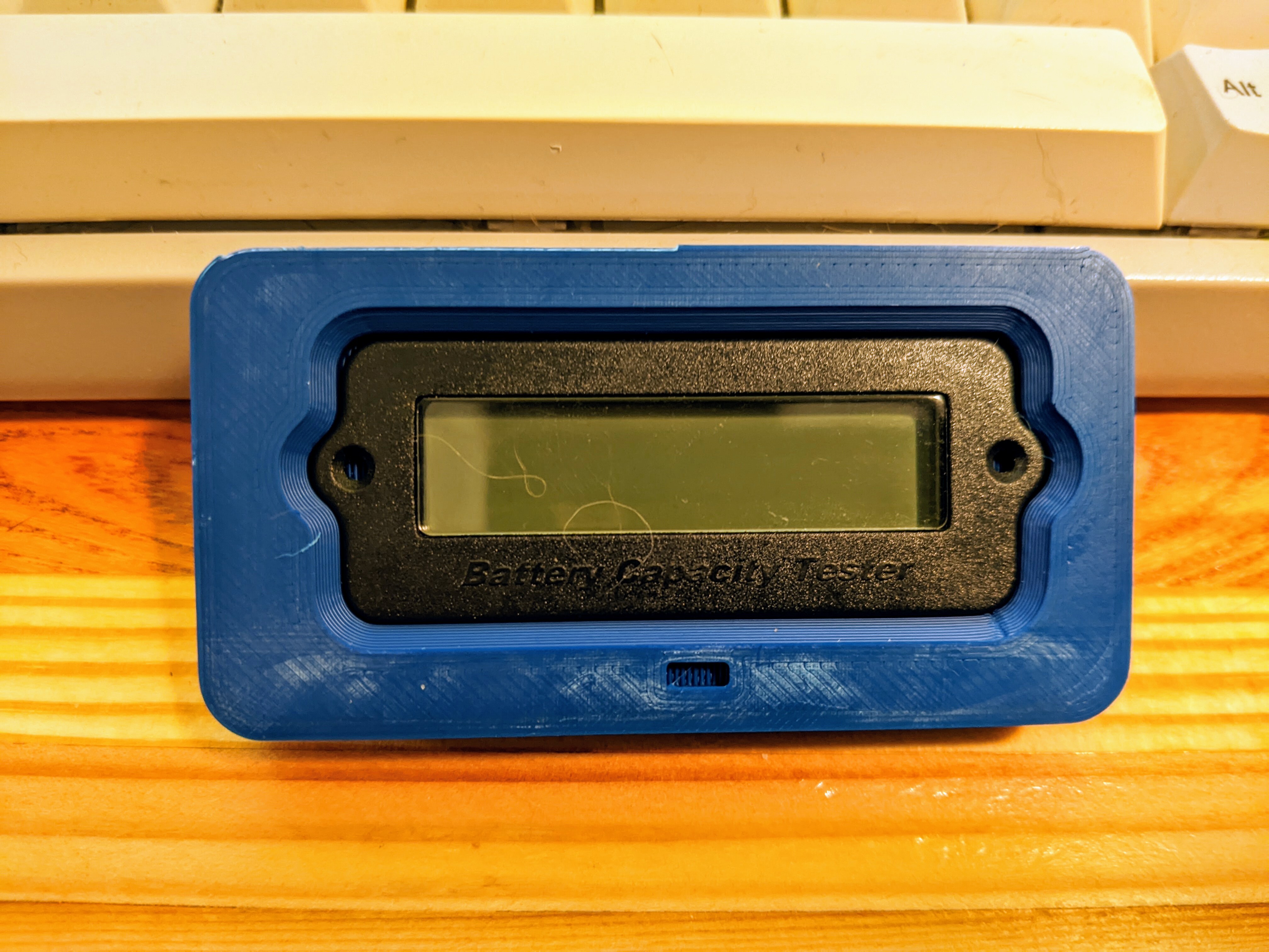
So are you saying you traced a photo, then printed multiple parts to get a trial-and-error fit? And you're trying to fit the blue part around the black part?
That seems extremely time consuming and wasteful. 3d printing lets you work this way but you'll get better results by planning out the part more carefully from the start.
The way I would do it is to identify the key measurements. This looks like a complex shape but it can be easily broken down into a few numbers.
First you obviously need the height, width and depth of the main rectangle. Then you need the screw hole diameter. From there, you can measure the distance from the screw hole border to the edge of the tabs that surround the screw hole, and use that to calculate the radius of that whole tab piece. These are all easy with calipers.
From there, there are tricks you can use to measure the corner fillet radius and the internal fillet radius where the screw tabs meet the main body, but also they look like they could be the same as the screw tab radius.
An important piece of info here is that those compound curves are usually just simple circular radii. They're easy to work with so designers will stick with them.
Try that and see if it looks right. If not, try whole-millimeter adjustments in the numbers till they look the same as your reference part. If you can't get it right that way, go to half-millimeter increments. People working in CAD software very rarely go to finer adjustments than that for superficial details like this, so it's usually easy to find the numbers they used.
Then you add a margin between the inner part and the part you're making, like say 1mm or even 0.5mm, and see if that looks right.
Then all that's left is to decide whatever measurements you need out of the piece you're making and go for it.
If you learn to set these parameters up in your CAD software you can easily adjust them until the part looks right.
