3DPrinting
3DPrinting is a place where makers of all skill levels and walks of life can learn about and discuss 3D printing and development of 3D printed parts and devices.
The r/functionalprint community is now located at: or [email protected]
There are CAD communities available at: [email protected] or [email protected]
Rules
-
No bigotry - including racism, sexism, ableism, homophobia, transphobia, or xenophobia. Code of Conduct.
-
Be respectful, especially when disagreeing. Everyone should feel welcome here.
-
No porn (NSFW prints are acceptable but must be marked NSFW)
-
No Ads / Spamming / Guerrilla Marketing
-
Do not create links to reddit
-
If you see an issue please flag it
-
No guns
-
No injury gore posts
If you need an easy way to host pictures, https://catbox.moe may be an option. Be ethical about what you post and donate if you are able or use this a lot. It is just an individual hosting content, not a company. The image embedding syntax for Lemmy is 
Moderation policy: Light, mostly invisible
view the rest of the comments


I haven't looked into this specific design and I'm no CFD expert, but I have played with designing and built several small empirical test setups to compare and contrast various designs for shrouds.
Don't put trust in CFD. These little fans are turbulent flow regime and nowhere near laminar. These two flow regimes are completely unrelated and laminar flow simulation is not relevant in the slightest. You can get turbulent CFD simulation software but they all cost many thousands of dollars as far as I am aware. The last time I went down this rabbit hole was a year or more back.
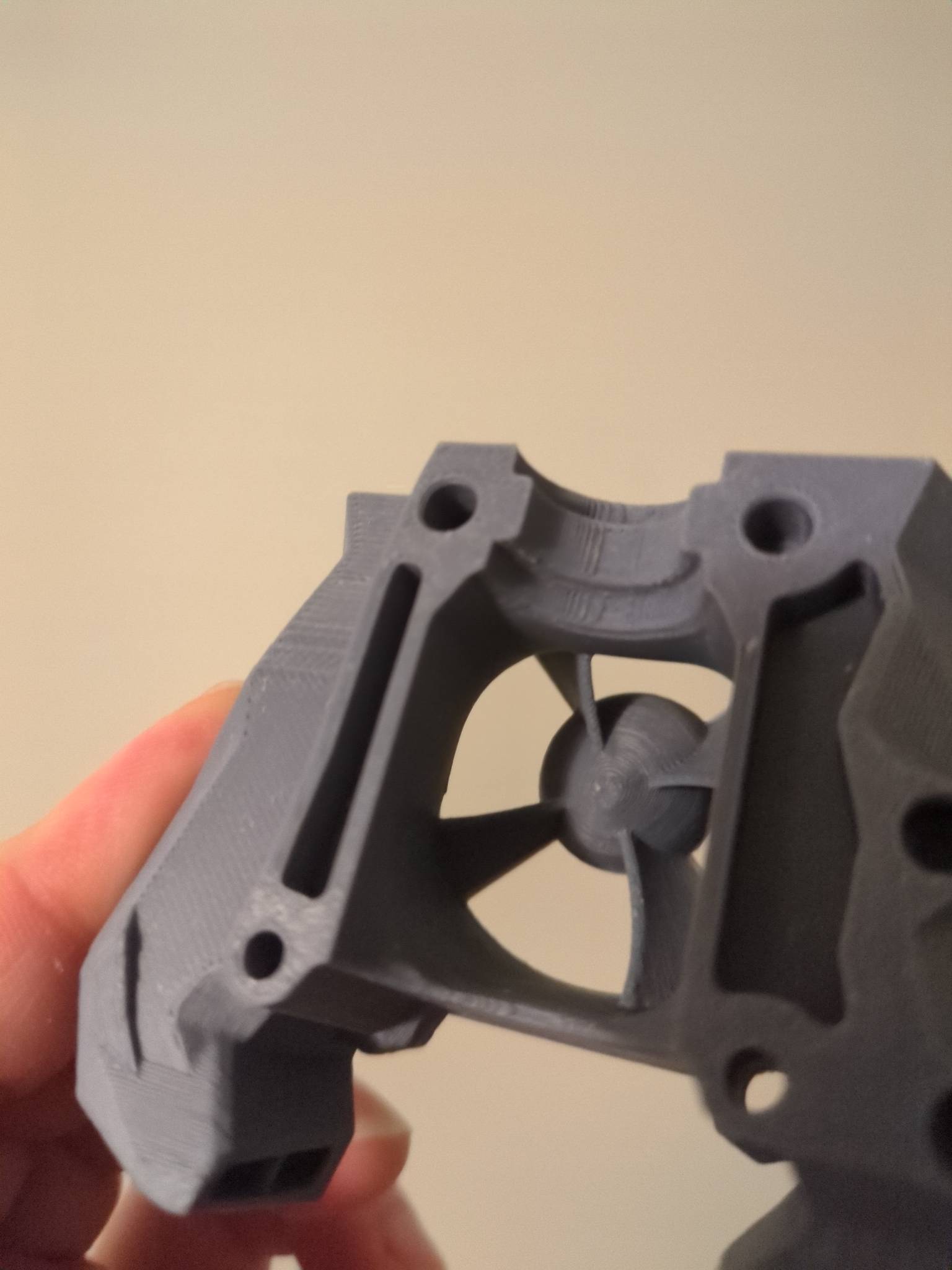
The boundary flow effect is a major factor in airflow, as is the total length of the system. The rough printed surface area of this design is likely hurting the total flow. Any sharp face angle transitions will cause eddies to form.
The deeper you get into real airflow design, the more you will find that almost everything in the 3d printing space is wrong. The best source of intuitive information I found was looking for info about HVAC duct systems in large buildings. You will find a good bit of info in that space from qualified engineers and academics, and HVAC duct flow is all in the turbulent regime.
Long before I got into 3d printing I was into hotrods and also worked for a bit at some machine shops building engines and porting heads. I was into trying to understand airflow in intakes, heads, and manifolds. I'm still no expert, but I can look at a design and see, intuitively it doesn't align with all of the super engineered stuff I've come across. I know that is super subjective, but like I said, the HVAC space can produce good info and rules of thumb equations about duct length, transition losses, and the impact of surface roughness on the boundary layer. Any basic info in these areas will make almost all designs in the 3d printing space seem like nonsense.
This guy's got the facts straight. Some 3D printers are in fact reasonably optimized, but also have to contend with pricing by way of complexity slowing down each print, plus post-processing... Easiest thing for most people to do is add a bigger fan. There will be a few situations where that's not possible.
Thanks. I'm still in the not even knowing what I don't know level on the topic so that helps my future researching.