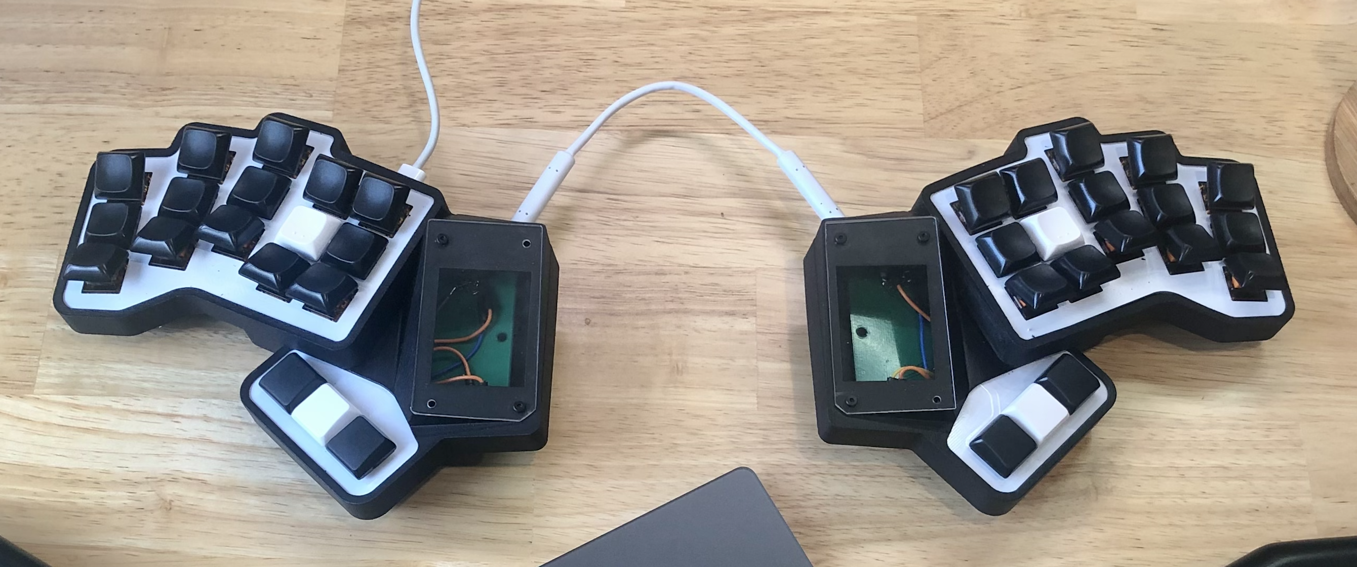
Tell me about your angled keys. This is the first I've seen them like this. What are they called?
ErgoMechKeyboards
Ergonomic, split and other weird keyboards
Rules
Keep it ergo
Posts must be of/about keyboards that have a clear delineation between the left and right halves of the keyboard, column stagger, or both. This includes one-handed (one half doesn't exist, what clearer delineation is that!?)
i.e. no regular non-split¹ row-stagger and no non-split¹ ortholinear²
¹ split meaning a separation of the halves, whether fixed in place or entirely separate, both are fine.
² ortholinear meaning keys layed out in a grid
No Spam
No excessive posting/"shilling" for commercial purposes. Vendors are permitted to promote their products/services but keep it to a minimum and use the [vendor] flair. Posts that appear to be marketing without being transparent about it will be removed.
No Buy/Sell/Trade
This subreddit is not a marketplace, please post on r/mechmarket or other relevant marketplace.
Some useful links
- EMK wiki
- Split keyboard compare tool
- Compare keycap profiles Looking for another set of keycaps - check this site to compare the different keycap profiles https://www.keycaps.info/
- Keymap database A database with all kinds of keymap layouts - some of them fits ergo keyboards - get inspired https://keymapdb.com/
They are custom angled risers I got printed. They fit between the switch and the keycap.
So they still push straight down? How does that feel?
It took a while to get used to them (like a day or two). But I’ve been using them on keyboards for a couple of years now, and it feels strange to not have them.
Take apart any old switch mode power brick, rip off the transformer and unwind the enameled copper wire. Use an Xacto knife to carefully and completely remove the enamel from the entire circumference and test if it wets with solder in 360° before adding it as a replacement.
For my own etched designs that need mechanically solid through holes and for repairs/mods where I need to make a soldering contact, I keep a set of brass micro rivets. The smallest ones I have are 0.9mm and work great with a 1mm hole in the PCB. If you've never seen or tried this, no special tools are needed. Place the rivet in the hole and use a pointy object like a dental pick to expand the back side.
Do you otherwise have no spare pins? Also you can do communication between halves with only a single pin, what protocol are you using?
The other thought is, does the LCD use i2c and are you using i2c between halves too? If so, does the LCD modules have a way to change their i2c address so they don't conflict? If so you should theoretically be able to have all of it share the same bus (the same 2 pins).
Oh that’s an interesting thought. All might not be lost after all! I’ll need to investigate.
At least it's usable. My last pcb I screwed up the gaetreon holes completely. Why do they make key switches so obnoxious.
True. I’ve not yet added any code to manage the per key RGB. Hopefully they all work as planned too.
