1
Arduino and other electronics projects info
125 readers
1 users here now
founded 1 year ago
MODERATORS
2
3
4
5
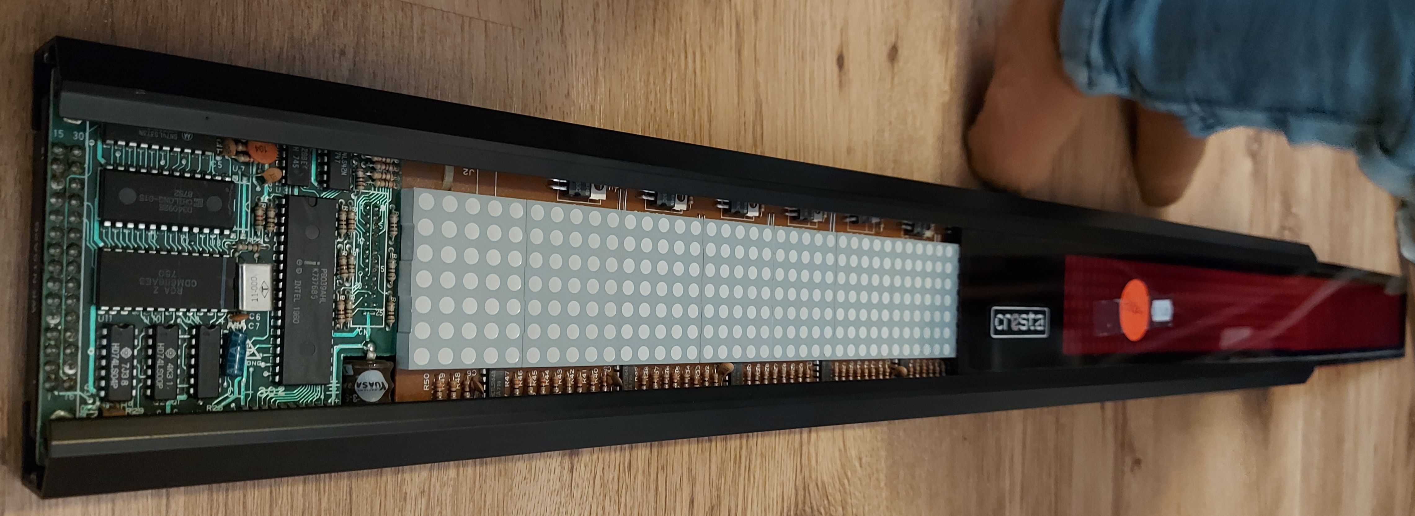
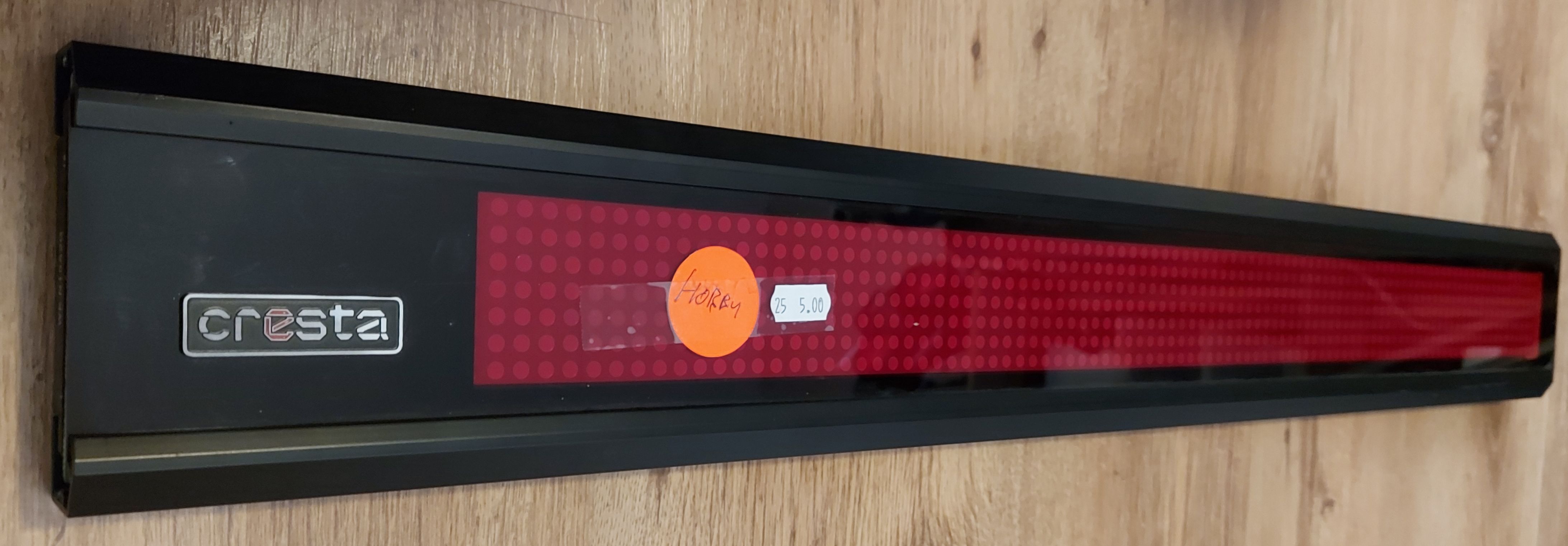
i found this lightbox without keyboard as the second hand store. i thought i'd see what i could do.
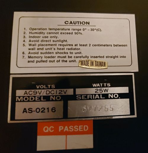
There's hardly any info on the Cresta AS-0216.
The websites i found, looking like the same (or similar) device;
- a Chilong "Ad-Pro AS-0216" https://www.amazon.com/AD-PRO-AS-0216-PROGRAMMABLE-LED-SIGN/dp/B00UDNDG6O
- a Brandless AS-0216 https://www.elektroda.pl/rtvforum/topic1584838.html
- This blog https://www.circuitsonline.net/forum/view/30396/1#highlight=cresta in search for AS-0216 material refers to http://www.kingpul.com.tw/ but that domain is no longer active.
- "Kingpul" brand website can only be seen via the internet-archive; https://web.archive.org/web/20051214082253/http://www.kingpul.com.tw:80/rh216r.htm lists the type "RH-216R" which seems comparable. But no manual is downloadable
- "Sigma ASC 333" is mentioned here https://www.hetlab.tk/artikelen/lichtkrant-protocol and states it is similar to the "Cresta RH-0214CR". This one has software for windows 95 available, and i could download the manual (via https://web.archive.org/web/20160904131325/http://anseyang.myweb.hinet.net/214CR.htm )
- https://elektrotanya.com/sigma_asc_333,as226_fenyujsag_software.zip/download.html It refers to this Kingpul site as well (only still internet archive) https://web.archive.org/web/20160904131325/http://anseyang.myweb.hinet.net/214CR.htm
- Someone tried some things on an AS-0216 http://www.nerdkits.com/forum/thread/1256/
- "HiTech AS-0216" is also one of it's names; https://forum.arduino.cc/t/controlling-a-old-school-led-message-sign-hitech-as-0216-with-a-uno/367646
There's a blog about a repair of a Cresta-0216;
- https://www.markgrob.nl/2021/04/cresta-as-0216-repair/comment-page-1/ But that device has a different print than mine.
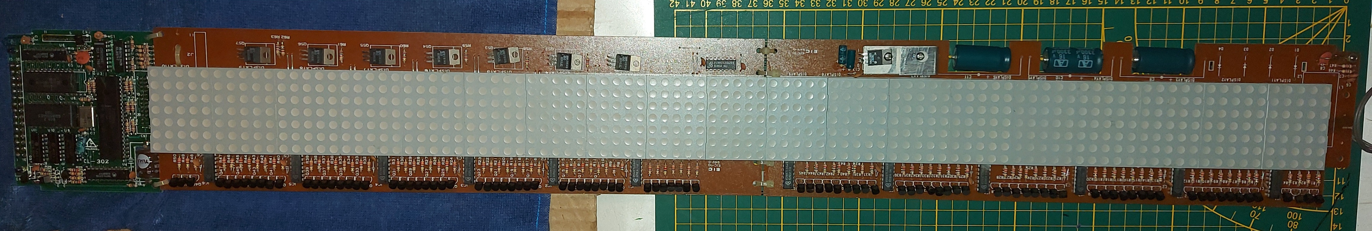
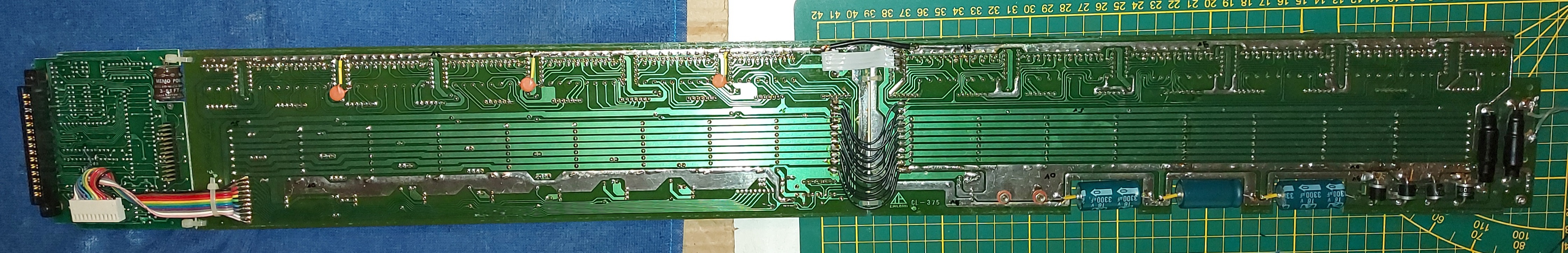
My device looks like this (pictures can be enlarged by clicking):

i'll be posting some update if i have them
6
7
I've got a few damaged hoverboards. They're not very good quality. Some work others go into error-state after a while.
To be able to do some fault finding i thought to try to readout what these sensorboards provide.
This is the exact model i have
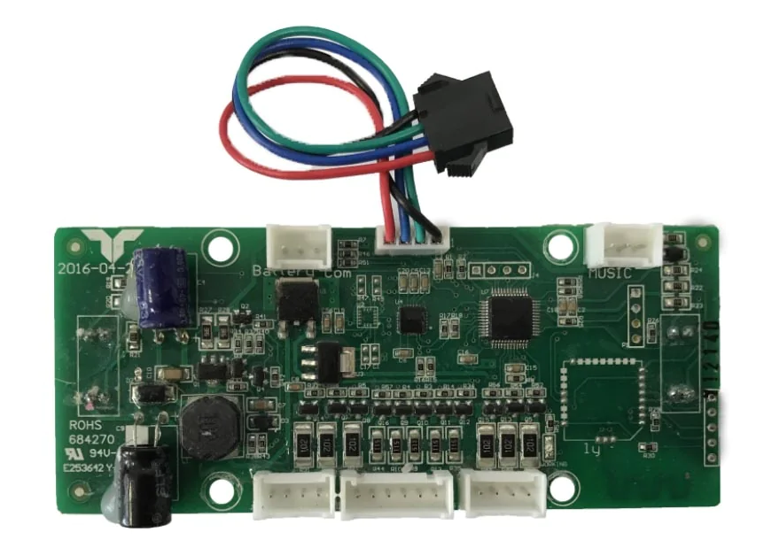
Sensorboard gyroscope taotao 684270 2016-04-20 (where i found the pics: https://www.voltes.eu/products/hoverboard-sensorboard-gyroscope-taotao)
i use the Arduino mega 2560, because it has multiple UART pins.
Baud rate
I first needed to know the baud rate. For that i found some online arduino code measuring the shorted pulse duration, and based on that determine the baud rate. Seems the board is communicating at 57600 baud.
which UART mode
To try to find out what UART mode is used, i created a program which determines the high/low durations of the data pin, and print it as a bitstream, hoping to be able to determine the mode. But i couldn't make sense of it(in hindsight, i can understand it, but i'm too much of a rookie). So i just tried the few available modes. None of the 5 to 8 databits modes produced anything useful.
9 bit data
Turns out the standard Arduino 8 bit UART modes don't work. i needed to try the 9 bit UART mode. For that i used an external library mentioned on this site: https://forum.arduino.cc/t/9-bit-software-hardware-serial/590266/8 Because this library sets an interrupt routine, i renamed the HardwareSerial9bit0.cpp file to HardwareSerial9bit0.cpp.txt so that in my sketch it didn't collide with the Arduino IDE's Serial which i used for debug printing to the Arduino console. The mode which worked for Serial91 is SERIAL_9O2 (9 databits, Odd parity, 2 stopbits )
Finding a frame
To find the start of a frame, i decided to look for a 0, then 2 times a non-0, and a 0 after the frame. For storing the UART data in a buffer, i used the CircularBuffer library by AgileWare v1.3.3 https://github.com/rlogiacco/CircularBuffer . I set it to store 512 integers. When Arduino finished 1 cycle, there are between 10 and 60 integers read into the buffer. But when i enable printing of packets to Serial, then it increases to about 70 - 80 per cycle which are available. When the cyclical buffer contains more then 10 integers, i test if it contains a valid frame, if not, i remove the head, and test again. Update: I changed the frame detection because an actual 0 angle would not be possible. So now it tests for #0 to be 0, #5 to be 0x5 or 0xA, #10 to be 0. Also, i now realize that UART overflows at 64 characters.. i.e. the code must be improved to be faster. /update
Data obtained
The data packets are formatted as
 * 000,102,002,102,002,01A,0B8,0B8,000,000,000,
 *     AA  BB  AA  BB  CC  DD  DD  EE  EE  FF
 * 000   = Start of frame
 * AA BB = LSB,MSB  forward backward angle
 * CC    = Status bits ( 0xA unpressed, 0x5 pressed, 0x20 Error/was upside down )
 * DD    = 9 bit unsigned 0..185..368 intertia left/right       rotation
 * EE    = 9 bit   signed -255.. +255 intertia forward/backward rotation
 * FF    = Start of next frame
Data issues
The doubling of the data in a single frame enables some error checking. I observed the next issue
AA   BB    AA   BB   CC  DD  DD  EE EE  | 'AABB as dec nr' || Bad
Angle reading is dodgy.. Bits are flipping on.offf
V     V    V     V
63 | 1E1 | 63 | 1E1 | 5 | B8 | B8 | 0 | 0 | -15773 ||
63 | 1F1 | 63 | 1F1 | 5 | B8 | B8 | 0 | 0 | -7581  || BAD
73 | 1E1 | 73 | 1E1 | 5 | B8 | B8 | 0 | 0 | -15757 || BAD
63 | 1E1 | 63 | 1E1 | 5 | B8 | B8 | 0 | 0 | -15773 ||
63 | 1E1 | 63 | 1E1 | 5 | B8 | B8 | 0 | 0 | -15773 ||
73 | 1F1 | 73 | 1F1 | 5 | B7 | B7 | 0 | 0 | -7565  || BAD
63 | 1E1 | 63 | 1E1 | 5 | B8 | B8 | 0 | 0 | -15773 || BAD
73 | 1F1 | 73 | 1F1 | 5 | B8 | B8 | 0 | 0 | -7565  || BAD
63 | 1E1 | 63 | 1E1 | 5 | B8 | B8 | 0 | 0 | -15773 || BAD
72 | 1E1 | 72 | 1E1 | 5 | B8 | B8 | 0 | 0 | -15758 ||
62 | 1E1 | 62 | 1E1 | 5 | B8 | B8 | 0 | 0 | -15774 ||
62 | 1F1 | 62 | 1F1 | 5 | B8 | B8 | 0 | 0 | -7582  || BAD
62 | 1E1 | 62 | 1E1 | 5 | B8 | B8 | 0 | 0 | -15774 || BAD
62 | 1F1 | 62 | 1F1 | 5 | B8 | B8 | 0 | 0 | -7582  || BAD
72 | 1E1 | 72 | 1E1 | 5 | B8 | B8 | 0 | 0 | -15758 || BAD
But i actually can't figure out which of the reading is 'BAD' i just picked the one which changed much in angle from the previous frame, while accelerometer(EE) says 0. i figured that if the angle changes much, then the accelerometer should also indicate movement.
Statistics
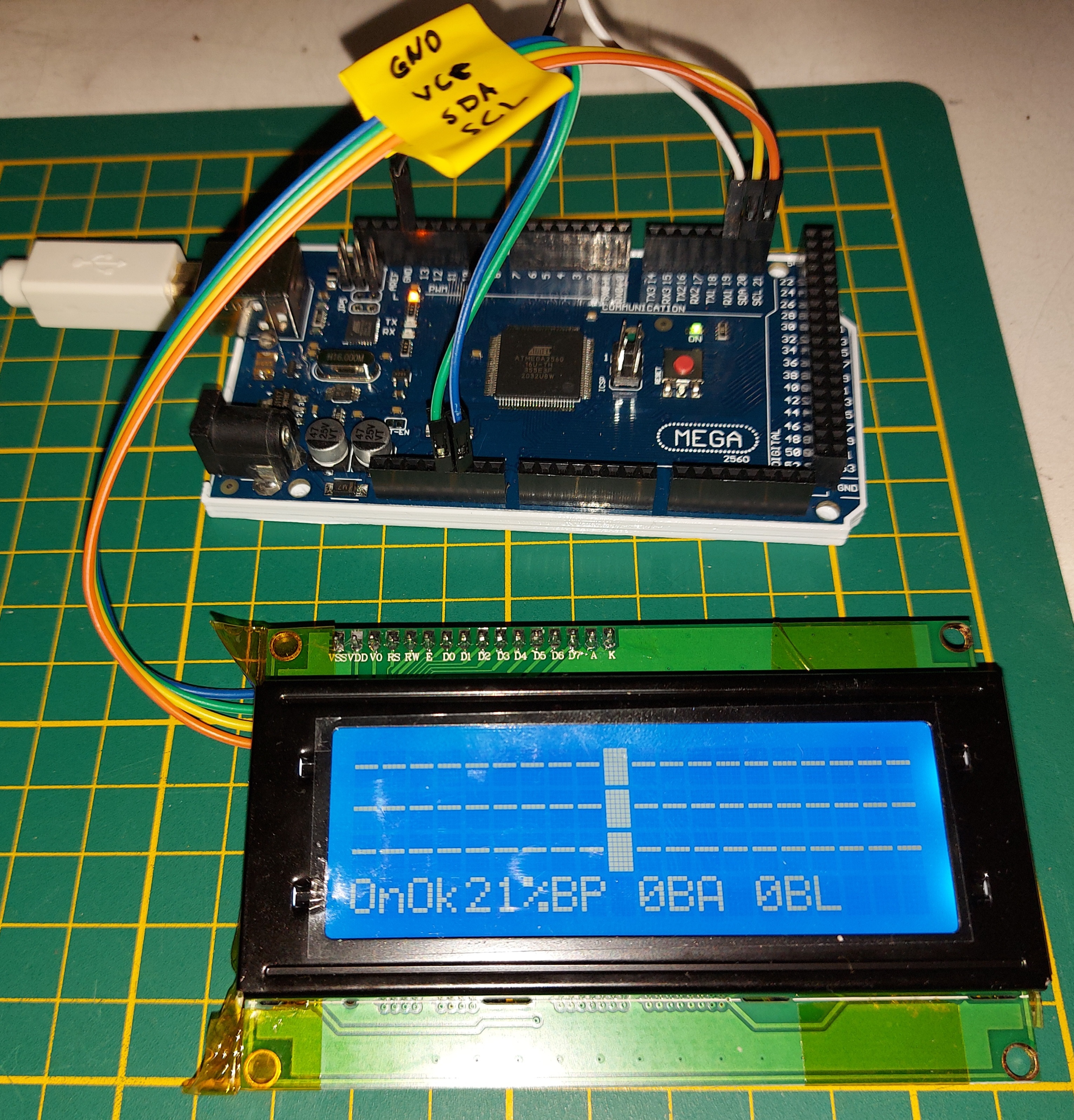
After logging the packages and trying to find a way to read only valid frames, i used an LCD 20x4 I2C screen to show some statistics. For that i used LCD Library by Frank de Brabander v 1.1.2 https://github.com/johnrickman/LiquidCrystal_I2C
I show a databar for the
- forward/backward angle
- forward/backward accelerometer
- left/right-turning accelerometer
and the following info
- Err/Ok (upside down etc)
- On/Off (standing on the pedals)
- %BP (Percentage Bad Packets. A packet is bad when the doubled data isn't the same)
- BA (amount of 'Bad Angle' packets)
- BL (amount of Bad Line incidents. i.e. not able to find the starting '0' data of a frame. Testing for nr #0 = 0(start) and #10 = 0(next start), and #1 and #2 are non-null.)
My total setup looks like this
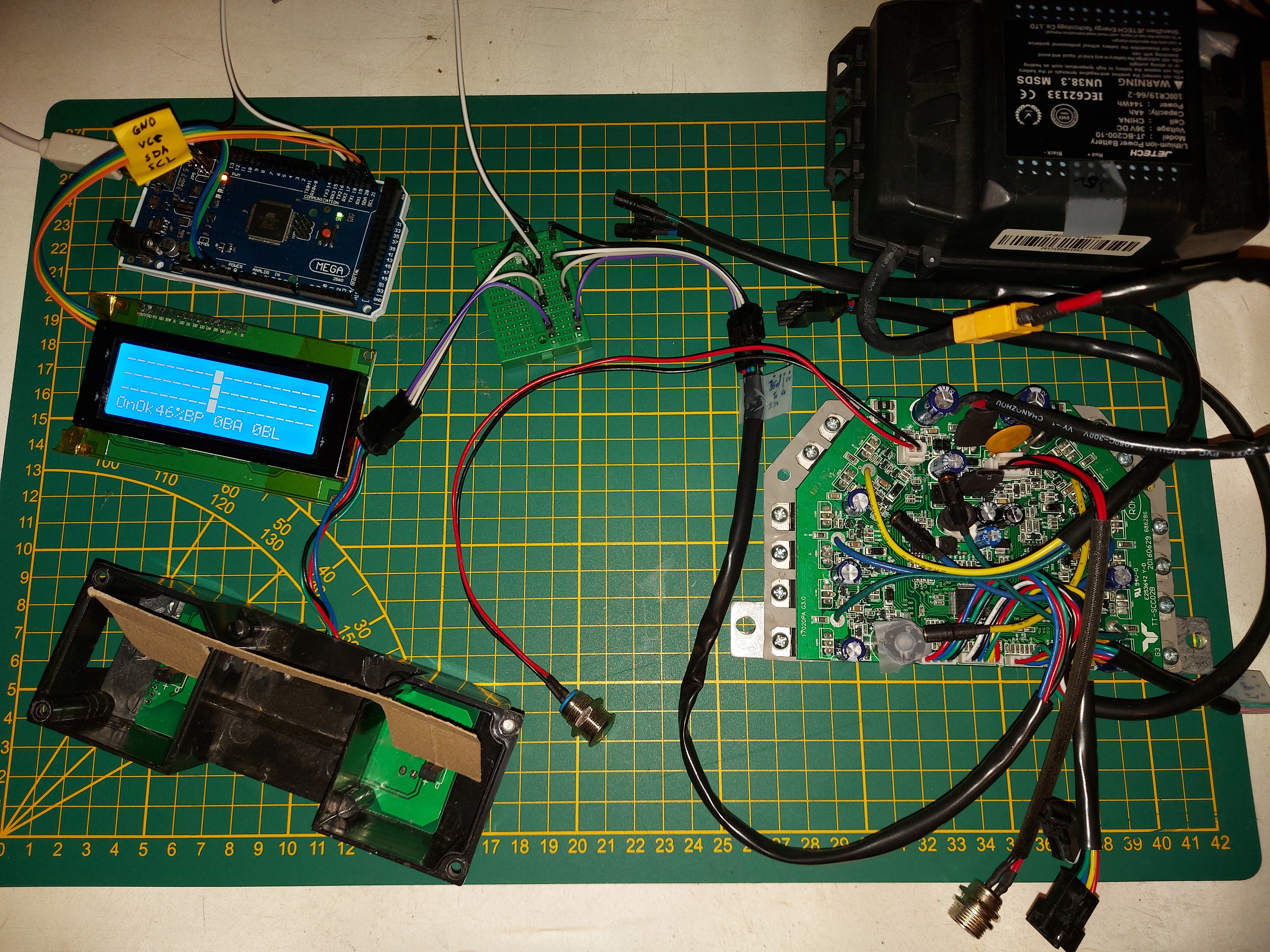
For the presentation not to take too much CPU time, the top 3 bars refresh every 100 msec, the bottom numbers refresh every 500 msec. i Also changed LiquidCrystal_I2C\LiquidCrystal_I2C.cpp to set the I2C speed to 400Khz by calling setClock()
void LiquidCrystal_I2C::init_priv()
{
	Wire.begin();
	Wire.setClock(400000); // Set I2C to 400Khz
	_displayfunction = LCD_4BITMODE | LCD_1LINE | LCD_5x8DOTS;
	begin(_cols, _rows);
}
Next up.. Trying to figure out what sensor-data is acceptable by the main board and which data makes the main-board go into error state.
8
9
10
11