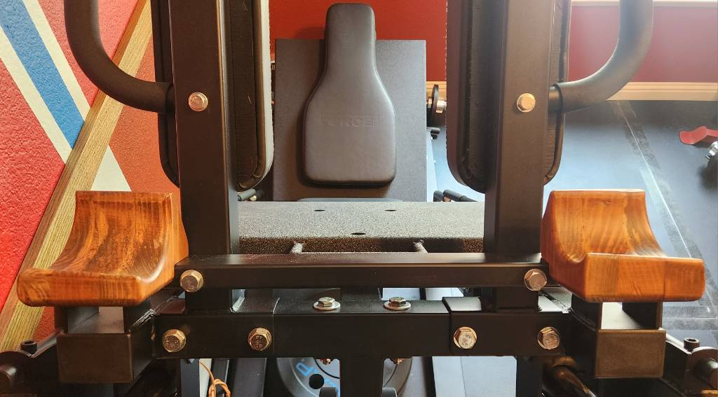
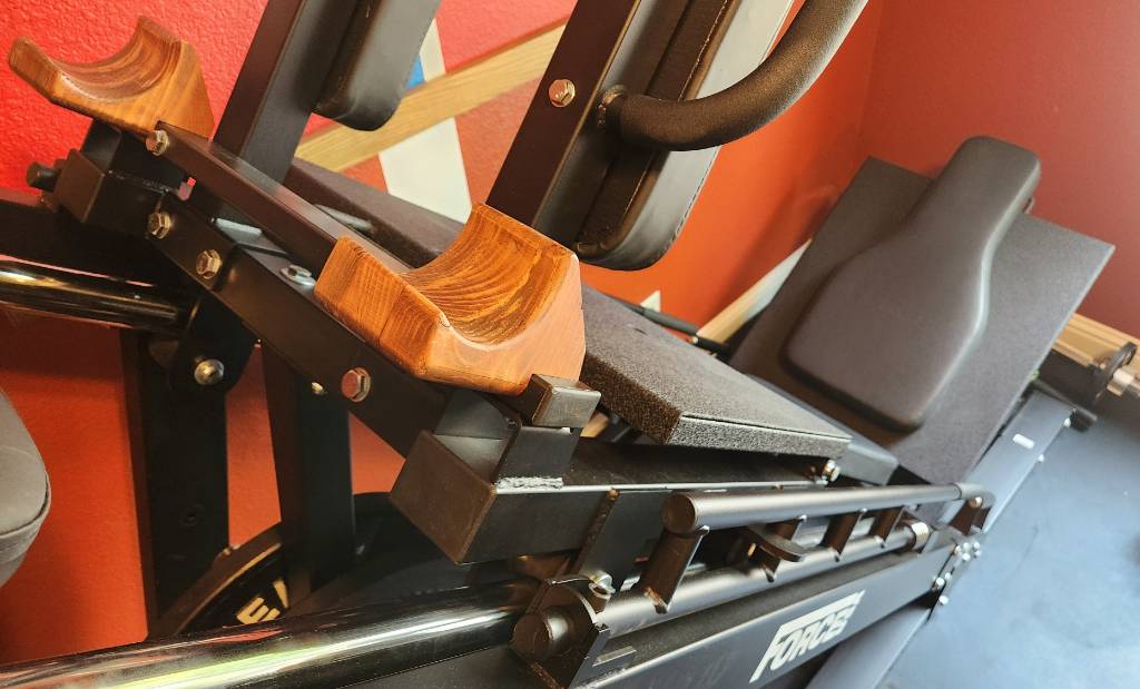
This is the story of how I turned a 15" Titan adjustable dumbbell to be 80 cm (31.5 inch) long. Why? Because I have a space-constrained home gym but still wanted a leg press, and so I had to remove its original barbell.
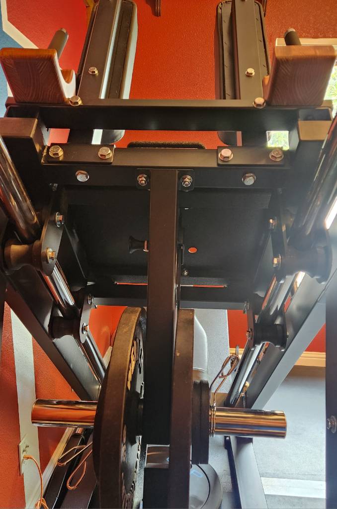
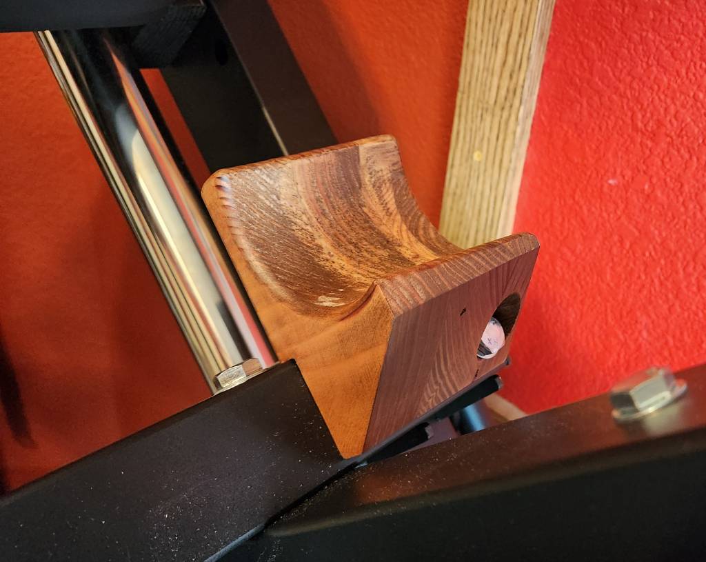
In its place, I built a pair of wood mounts for a normal barbell to rest upon, covered in that earlier post. However, since this machine is wall-adjacent, such a barbell would have to fit inside the width of the leg press, so about 80 cm. But must also be wider than the spacing from outside-edge to outside-edge of the wood mounts, which is 60 cm.

Such a short barbell -- or long dumbbell -- does not readily exist commercially, with the narrowest one I've seen being 48 inch barbells, which are still too wide. So I decided to build my own, using my spare Titan dumbbell as the base.
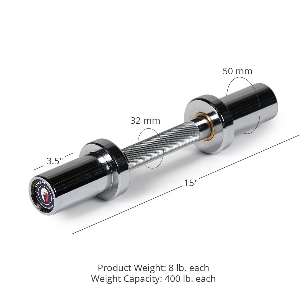
To start, the Titan dumbbells are excellent in this capacity, as the shaft diameter is 28 mm -- not 32 mm as the website would indicate -- which is a common diameter, if I am to cut short a cheap barbell to replace this dumbbell's shaft.
In keeping with my preexisting frugality, I purchased a cheap 1-inch barbell, hoping that it adopts the Olympic 28 mm shaft diameter, and not the 29 mm deadlift bar shaft diameter, as the Titan collars have small clearances. Matching neither, I find that this bar is closer to 23 mm, which although will fit into the existing collars, poses its own issues.
Nevertheless, this 7 ft barbell can conveniently be cut in half to yield two 42 inch segments. And then the included bar stops can be loped off, and then the length further refined to 77 cm, thus hiding the marks from the bar stop within the Titan collars, and also centering the (meh) knurling from the cheap bar.
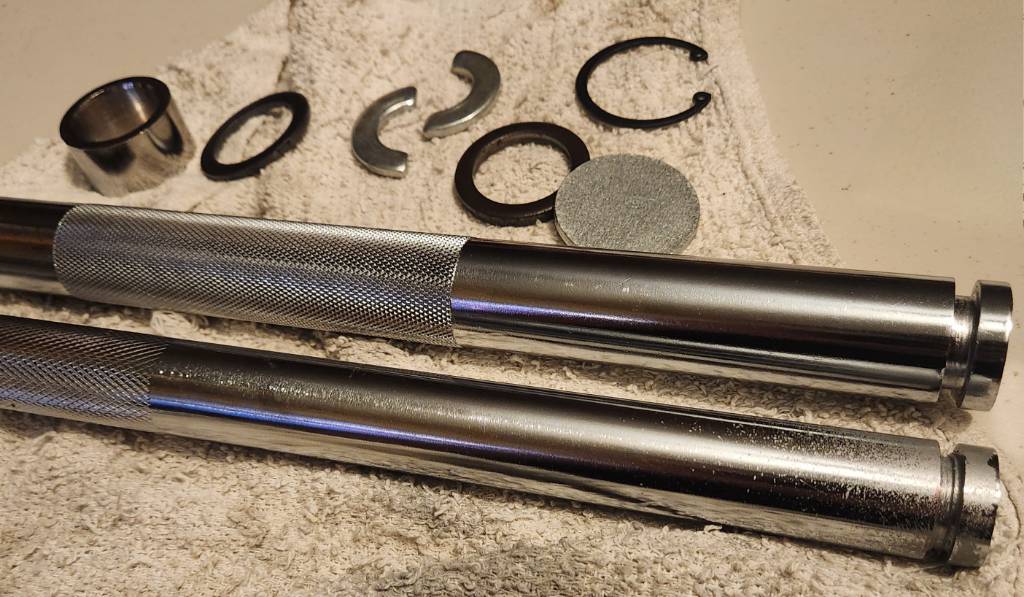
But perhaps a picture will be more explanatory. Here, the original collar is dismantled at the top, showing the original shaft with a groove cut into it, about 1/4-inch from the end. Into that groove would fit two half-rings with an inner diameter of 20.4 mm and an outer diameter of 40 mm. In fact, all the parts inside the collar use 40 mm outer diameter, except the spacer cylinder, which is smaller at 37 mm. All of these parts are held captive within the collar using the C-ring and the geometry of the collar itself.
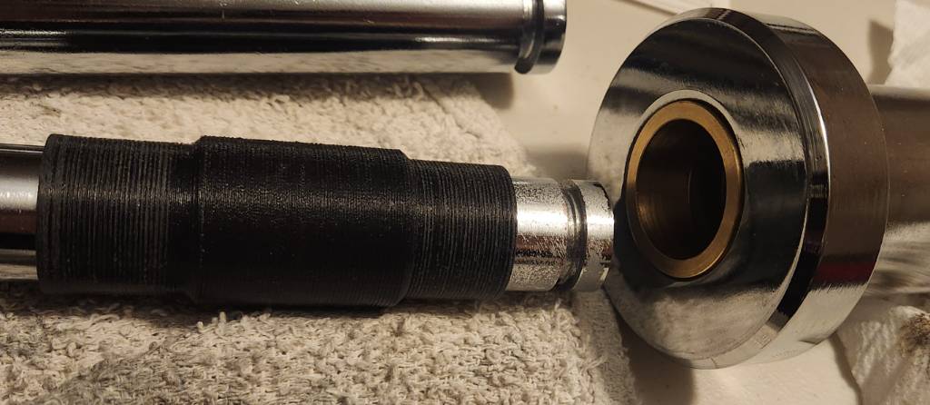
To deal with the difference between the collar expecting 28 mm, and the cheap bar's 23 cm, I designed an ABS 3d printed part in FreeCAD to act as a bushing, upon which the original Titan brass bushing will ride upon. This ABS bushing is held captive by way of its center bulge, which fits within the dead space inside the collar.
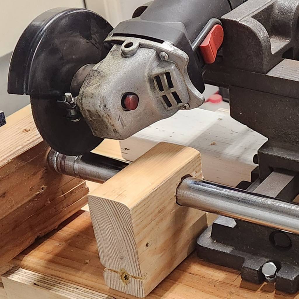
As for how I cut the groove into the end of the new shaft, I still don't own a lathe. So the next best is to mount an angle grinder onto a "cross slide vise" taken from a drill press, with the shaft secured in a wooden jig to only allow axial rotation manually. The vise allows precision control for the cutting wheel's depth, with me pausing frequently to measure how close the groove is to the desired 20.4 mm inner diameter. This is.... not a quick nor precise process. But it definitely works.
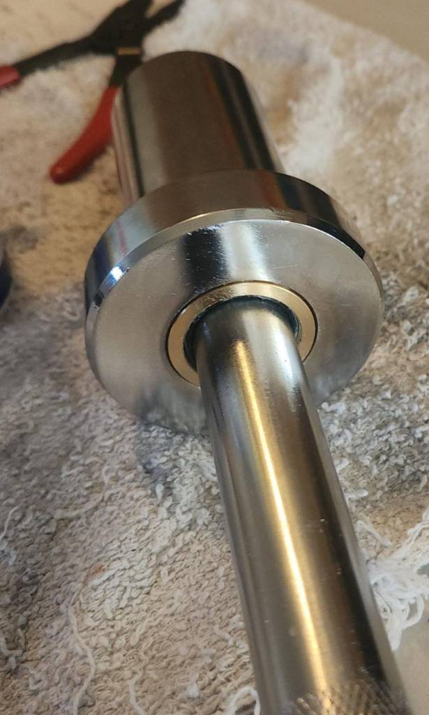
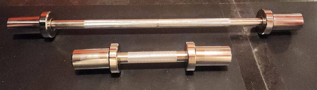
After reassembling both collars onto the new shaft and lubricating with white lithium, the final result is a long dumbbell (or short barbell) with Titan's 3.5 inch collars on the end, with 63 cm of shaft exposed and 80 cm from end to end. The ABS bushing is remarkably smooth against the brass bushing, after some sanding with 180 grit. The whole dumbbell weights 5.48 kg empty.
Here is the comparison with the stock Titan dumbbell. It's pretty amazing how the knurling conveniently lined up. It fits well onto the wood mounts of the leg press.


But why would I do all this just to add a weirdly long 3.5-inch collar dumbbell to a leg press, when it already can accept weights underneath the carriage? I will answer that in a follow-up post.


My prior comment on hydrogen mobility:
With that out of the way, I'm skeptical as to the benefits touted on the HydroRide website. Specifically, the one about storage:
This might be true in static conditions, but hydrogen automobiles have to vent some of the hydrogen while parked, simply to deal with the buildup of hydrogen gas, since even with excellent insulation, the liquid hydrogen will eventually get warm and evaporate into gaseous hydrogen, building up pressure. The fact is that automobiles must withstand broad environmental factors, especially temperature. And we expect bicycles to do the same: how the hydrogen tank would behave in warm climates is unclear.
There's also not that much hydrogen in the tank. The website appears to indicate 20 grams. At 33.6 kWh/kg, the total energy in the tank would be 672 Wh, putting it at par with electric bikes of similar range and speed. Any hydrogen losses would be balanced against battery capacity loss over time.
Overall, as the article states, the target audience of rental operators might still be inclined to go with battery electric bikes rather than hydrogen. Requiring a supply of pure water in addition to electricity at charging locations -- compared to just electricity for battery charging -- is an extra logistical consideration. The "charge" time of 5 hours for 20 grams of hydrogen is also a potential issue.