this post was submitted on 02 Aug 2023
40 points (97.6% liked)

ErgoMechKeyboards

5634 readers
26 users here now

Ergonomic, split and other weird keyboards

Rules

Keep it ergo

Posts must be of/about keyboards that have a clear delineation between the left and right halves of the keyboard, column stagger, or both. This includes one-handed (one half doesn't exist, what clearer delineation is that!?)

i.e. no regular non-split¹ row-stagger and no non-split¹ ortholinear²

¹ split meaning a separation of the halves, whether fixed in place or entirely separate, both are fine.
² ortholinear meaning keys layed out in a grid

No Spam

No excessive posting/"shilling" for commercial purposes. Vendors are permitted to promote their products/services but keep it to a minimum and use the [vendor] flair. Posts that appear to be marketing without being transparent about it will be removed.

No Buy/Sell/Trade

This subreddit is not a marketplace, please post on r/mechmarket or other relevant marketplace.

Some useful links

founded 1 year ago
MODERATORS
 

Having always been somewhat annoyed I can't simply place a Pro Micro (or for that matter any other controller) over on top of a hot-swap socket without either turning it sideways, loosing pins, or some other creative solution.

So after trying to find other smaller controllers, but always ending up with a compromise, I finally got fed up with it, and started designing one of my own that is just large enough to fit the purpose.

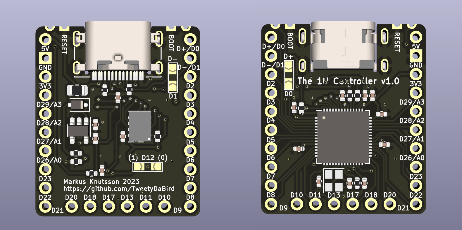
RP2040 powered of course, and with a mid mount USB type C, the design is extremely low profile and fairly barebones with no status LED, no buttons, etc. making it easy and cheap to produce. And with 26 pin, there are 23 IO pins available for matrix and other things. VBUS detection for easy use with split keyboards, but beyond that stripped of anything fancy.

The boot/reset signals are available as castellated connections next to the USB, and only really meant for the first flashing/emergency flashing, as the rest would be handled by tapping a keycode to enter bootloader from within QMK/ZMK.

Edit: Added D+/- as jumpered breakouts on pins, se below. Also added a pin high/low for assigning sides on a split (useful for handwiring)

top 12 comments
sorted by: hot top controversial new old
[–] [email protected] 2 points 11 months ago (1 children)

any chance the D+/- lines are broken out to a couple pins?

[–] TweetyDaBird 1 points 11 months ago* (last edited 11 months ago) (1 children)

I wasn’t planning on it since sacrifices two pins.

And seeing as the USB port is available to place by the edge very easily as you can place the controller over any key.

To explain, the USB port should end up needing only 3-5 mm edge on a sandwich case, or a hollow similar to how most pcb’s place it on a CNC/3d case.

Any particular reason beyond that? I’m open to reasonable compromises.

Btw, I can easily pull them out to a pair of pads, there is space for that.

[–] [email protected] 1 points 11 months ago (2 children)

just thinking about those designs where a case is wanted, but the position of the usb port isn't ideal. not one of those things that I think is required to make this a great controller option, just something a lot of controllers don't have and I've wanted for a bit.

[–] tubbytwins 1 points 11 months ago

I will second this request. I might not personally need this (yet) but it is a good option.

[–] TweetyDaBird 1 points 11 months ago* (last edited 11 months ago)

How about this then? (No promises on signal integrity of that USB signal, we are pushing limits)

Just keep in mind, that placing the controller not at an edge, will likely make the USB port interfere with the next socket, it's not really meant for that. Meaning you should probably de-solder the port then. Also, by powering through the 5V/GND pins, you negate the VBUS detection, and there simply aren't enough pins/space to break that out as well, so it's a compromise.

[–] tubbytwins 1 points 11 months ago* (last edited 11 months ago) (1 children)

Very cool. It looks like this will probably accommodate hot-swap sockets for both MX and Choc switches - correct?

[–] TweetyDaBird 1 points 11 months ago

It should, at least as long as we are talking about choc switches on an MX spacing, or a dual footprint design, as the pin headers are spaced for that. Otherwise there will probably be interference, or very, very close to it at least.

[–] [email protected] 1 points 11 months ago (2 children)

I don't understand the issues that prompted you to develop this, can you explain them a bit more? What hot-swap connector are you using this with?

Of course making a cool new board can simply be motivated be a desire to do so 😀.

[–] [email protected] 9 points 11 months ago (2 children)

If you want to put a controller on the underside of a keyboard, like the promicro, you can do it with just a standard MX or choc footprint by straddling the switch footprint. But if you swap the switch footprint with a kailh hotswap socket footprint the pads overlap with the promicro's through holes. So to keep the promicro under the switches you'd need to rotate it or remove some of the pins from the footprint, giving you less IO. This is designed to be able to be placed over the hotswap footprint.

[–] danieldk 2 points 11 months ago* (last edited 11 months ago)

Thanks! The confusing thing in the original message is that, in context, hotswap socket makes you think of a hotswap socket for the microcontroller itself, not a switch.

[–] TweetyDaBird 1 points 11 months ago
[–] TweetyDaBird 8 points 11 months ago

I guess an image says more than a thousand words?