this post was submitted on 27 Aug 2024
6 points (87.5% liked)

HVAC/R technicians and affiliated trades

92 readers
1 users here now

This is intended to be for hvac technicians and with hvac technicians in mind. Please refer to c/hvacadvice for out of the trade conversation, requests for help and whatnot.

founded 1 year ago
MODERATORS
 

cross-posted from: https://lemmy.dbzer0.com/post/26703241

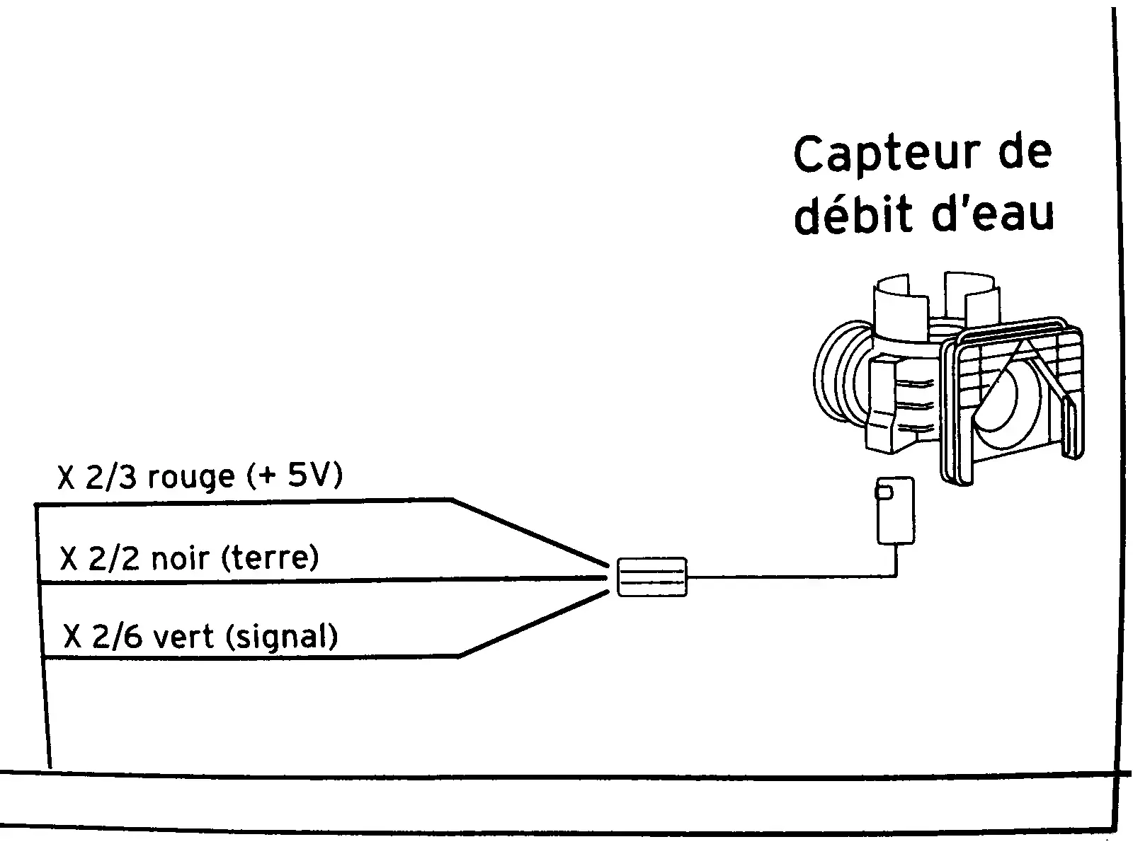
This diagram is from the service manual of a combi boiler. It’s a flow sensor which detects whether hot water is running, which is then used to trigger on-demand heat and switch a diverter to take radiators out of the loop.

In English, the diagram shows:

  • X ⅔ red wire (+5V)
  • X 2/2 black wire (ground)
  • X 2/6 green wire (signal)

I need to know what those fractions mean. I took the voltage measurements in this video:

I cannot necessarily trust the model in that video to have the same specs as mine. My voltmeter detected 4.68 V on the red input wire showing that the sensor is well fed. The green “signal” wire is supposed to be 0 V at rest and 2 V with water running (or I think the reverse of that is used in some models). In my case the green wire is ~1.33 V at rest and ~0.66 V when water is running. I need to know if these readings are normal as I troubleshoot this problem.
update


@[email protected] gave the right answer. Someone in another cross-post helped solve the underlying problem.

top 4 comments
sorted by: hot top controversial new old
[–] synapse1278 4 points 2 months ago* (last edited 2 months ago)

I believe "X #/#" are references that you will find on other pages of the schematic to indicate where these cables are connected too. Not so sure tho ...

Edit: indeed the letter X is standard designation for connectors and pins, and the numbers are references to cables.

[–] [email protected] 2 points 2 months ago

Man some of these trolley problems are getting really abstract... I'd go for the vert since I'm a fan of rouge and noir, but I have no idea what the payoff is at the end of the line

[–] [email protected] 1 points 2 months ago (1 children)

Without further information it's really hard to say. My first thought was those fractions are the gain the controller is expecting or maybe a tolerance of some kind. Could be some weird type of connection notation I'm not familiar with.

Health and safety warning: if you are unsure of what you're doing call a professional. It's better to ask for help than to burn down your home or get yourself or someone else hurt/killed.

What I might do if I was in your situation would be to hook up the 5v and common to the sensor. Then short the signal to the 5v with a potentiometer. Start with a really high resistance and slowly lower the resistance while observing the voltage drop over the pot and the boilers behavior. Basically your simulating the input. That'll tell you what the system is expecting from that sensor.

[–] [email protected] 3 points 2 months ago* (last edited 2 months ago)

Thanks for the effort. But actually @[email protected]’s answer is right. It turns out the diagram is misleading by putting “X2”. It’s just an abbreviated label for where the wire ends up on the circuit board; which for the green wire would be more verbosely written as “connector X2 pin 6”. So the diagram only tells me where the wires lead to not what the measurements should be. And in fact it’s disappointing that the service manual actually says nothing about what the voltage reading should be. It’s apparently undocumented.