this post was submitted on 27 Aug 2024
6 points (87.5% liked)
HVAC/R technicians and affiliated trades
92 readers
32 users here now
This is intended to be for hvac technicians and with hvac technicians in mind. Please refer to c/hvacadvice for out of the trade conversation, requests for help and whatnot.
founded 1 year ago
MODERATORS
you are viewing a single comment's thread
view the rest of the comments
view the rest of the comments

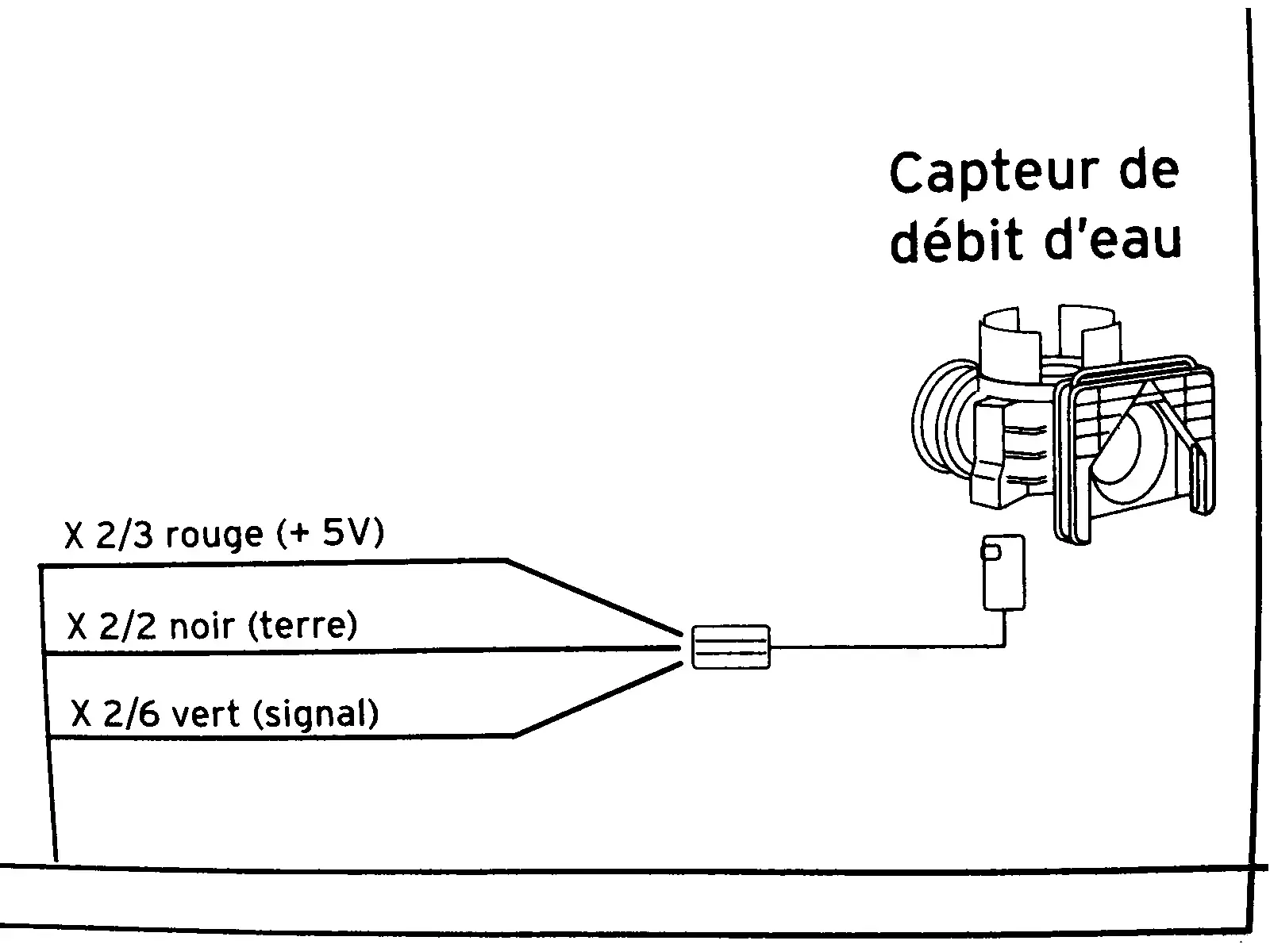
Without further information it's really hard to say. My first thought was those fractions are the gain the controller is expecting or maybe a tolerance of some kind. Could be some weird type of connection notation I'm not familiar with.
Health and safety warning: if you are unsure of what you're doing call a professional. It's better to ask for help than to burn down your home or get yourself or someone else hurt/killed.
What I might do if I was in your situation would be to hook up the 5v and common to the sensor. Then short the signal to the 5v with a potentiometer. Start with a really high resistance and slowly lower the resistance while observing the voltage drop over the pot and the boilers behavior. Basically your simulating the input. That'll tell you what the system is expecting from that sensor.
Thanks for the effort. But actually @[email protected]’s answer is right. It turns out the diagram is misleading by putting “X2”. It’s just an abbreviated label for where the wire ends up on the circuit board; which for the green wire would be more verbosely written as “connector X2 pin 6”. So the diagram only tells me where the wires lead to not what the measurements should be. And in fact it’s disappointing that the service manual actually says nothing about what the voltage reading should be. It’s apparently undocumented.