Mostly the same post as on r/flashlight in order to bring content here.
Back in 2020 I had an idea for modding an Astrolux MF01 for tint ramping with Lexel’s 4S buck driver, his MF01 driver was single ouptut but the two paralleled buck drivers on board could be separated for dual output with a simple modification, well that’s he said since at the time I wasn't very knowledgeable about drivers. So I bought one MF01 and asked to be put on the waiting list for a driver.
If you don’t know who Lexel is he was at the time one the driver experts at BudgetLightForum and offered FET+7135 and buck drivers for various lights. Sadly not long after he had some health issues and decided to take some time off BLF. Hopefully he is well now even if he is not on BLF anymore.
Anyway it wasn’t a problem for me since I had other projects and I would soon start on my own drivers.
Start of 2022 I remembered I had that light and thought I should design a dual buck driver for it, it was the middle of the chip shortage and buck ICs were especially difficult to find, fortunately after scouring Mouser and Digikey I found a pretty good one : SIC431, a 20A buck from Vishay, up to 24V input voltage and 6/2mΩ integrated FETs which is very good and should allows very high efficiency. So I started designing a driver based on this.
One particular element of the mod was the MCPCB, I could use the original MCPCB and modify it from 6S3P (3 groups of 6 series LED in parallel) to 2x3S3P but that would require a lot of trace cutting and jumpers. One way to make it easier would be to make a driver with high side current sensing, this means that the sense resistors are not placed on the negative side, but on the positive side, before the LED+wires. In this case the LED- wires don't need to come back to the driver and can be directly connected to the body (=batt-). There would still be some cuttings/jumper but much less, the LEDs would be grouped together 3 by 3 though and if possible I wanted to get better mixing.
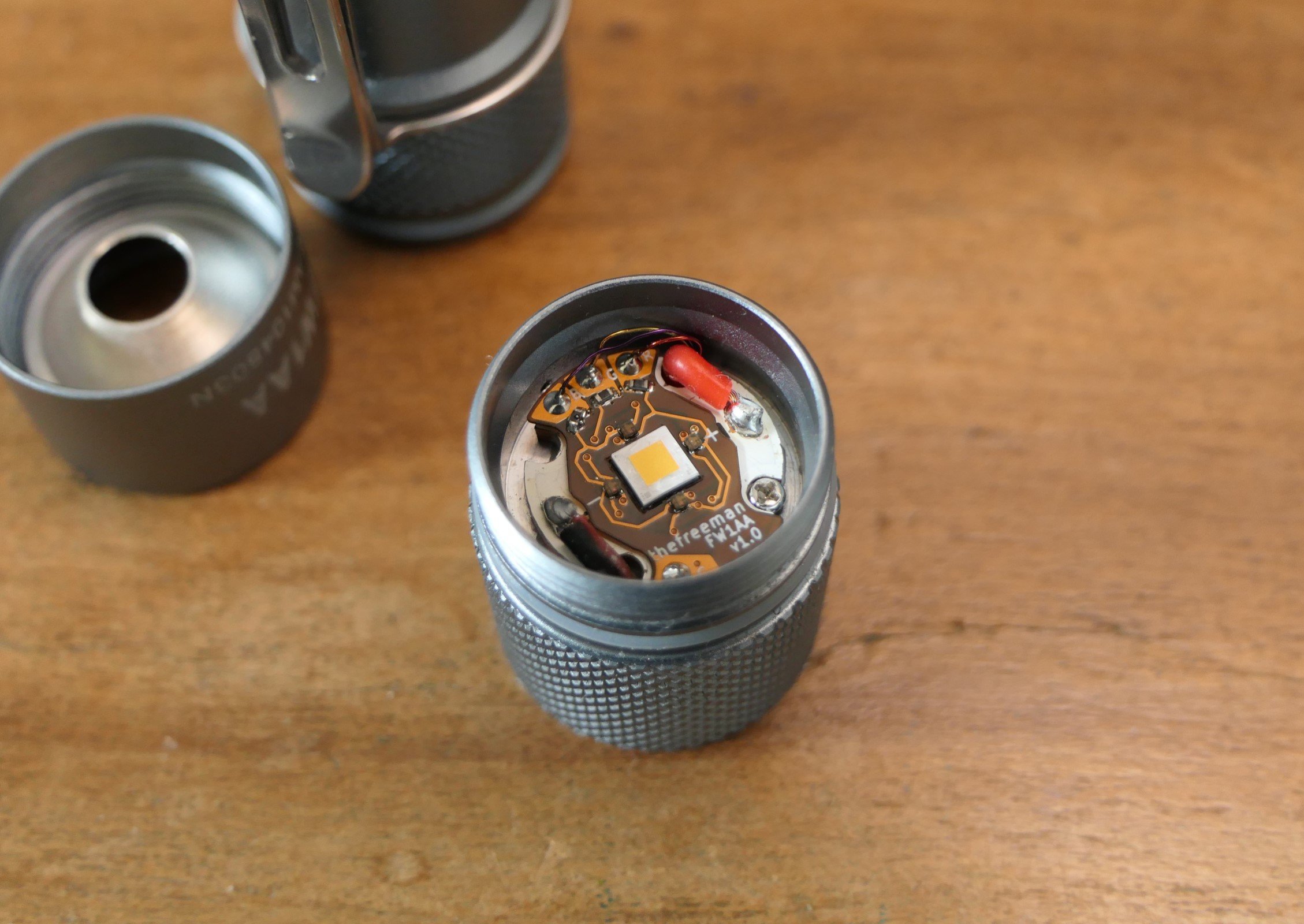
I took this occasion to experiment with something I wanted to do for some time : making a Direct Thermal Path (DTP) MCPCB with a cheap aluminium PCB. DTP means that the central thermal pad of an LED is directly soldered to the copper base of the MCPCB, allowing very low thermal resistance and thus driving the LED at higher current with lower temperature (higher performance). The majority of high power lights use DTP MCPCBs.
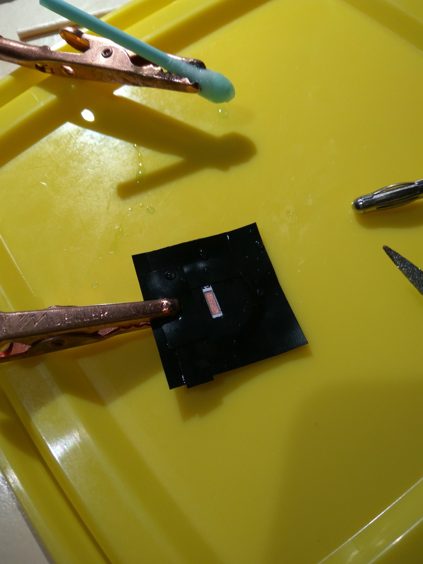
The idea was to remove the dielectric layer under the thermal pads and then copper plate the aluminium. Aluminium can’t be directly electroplated due to its alumina layer though, so the first step is to use a ”zincating” solution that removes the alumina, prevents it from reforming and allows copper electroplating with an alkaline copper solution, after a thin layer of copper has formed we can use an common acidic solution which plates faster.
I tried that on a single LED PCB first and it worked! So I finished designing a nice 2x 3S3P alu MCPCB, which I ordered from JLCPCB for next to nothing (2$, most of the actual cost was shipping).
Plating 18 LED pads ended up much more work than I thought, the zincating step was very finicky and I couldn't do the process in one go, I had to do each pads individually and a lot of time the copper wouldn't adhere, still after retries I eventually plated all of them. After getting the thin layer of copper I electroformed the pads so they could be (nearly) flush with the other pads, about 0.2mm of copper to grow.
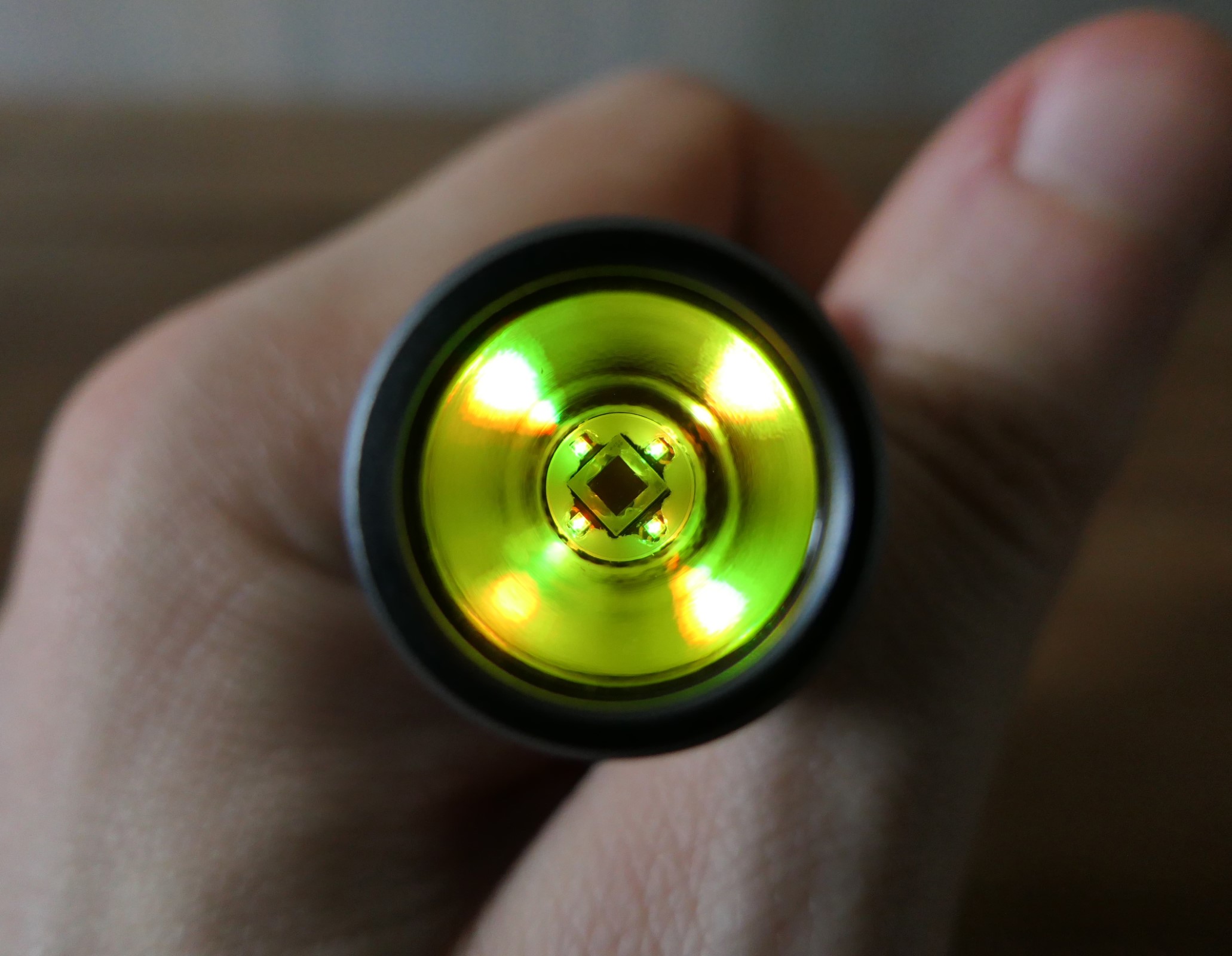
Dielectric removed :

Electroforming :

Final result :

Back to the driver I finished designing it after a couple of months (worked on and off on this) and assembled it. And then I left it in my driver bin for a year...
Sometimes I get nervous before testing a driver, like if it doesn’t work and I have to do a lot of troubleshooting (worse part), which leads to procrastination... usually that lasts only 1-2weeks so one year is a bit exceptional 😅

Anyway I tested it recently and it works, it’s also very efficient, 98% peak efficiency and more than 97% at full power (170W per channel, 5.33A per LEDs). Although I decided to set it to ”only” 100W per channel, 3.33A per LEDs which I thought was more reasonable.
Output/Efficiency graph :

Output/Efficiency table :

LEDs reflowed onto the MCPCB, 519A 2700K and 5700K :

I also designed a RGB aux board, Head assembled :

the cell carrier was originally 2S, I modified it to 4S and bypassed all the springs for lower power losses :

Warm channel ON :

both :

Aux LEDs :


C'est beaucoup mieux que les autres apps que j'ai testé et surtout elle est adaptée aux tablettes, par contre les prix sont un peu élevés.