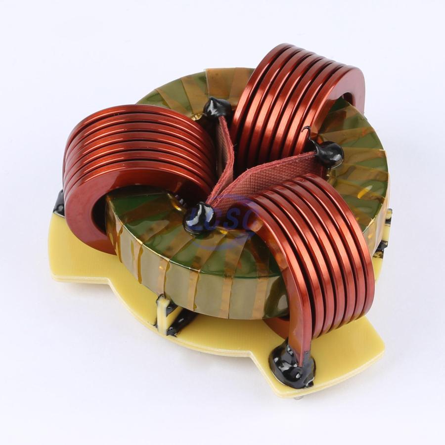
This is a beautiful work of art! Can you ELI5 what this is, please?
Electronics
Projects, pictures, industry discussions and news about electronic engineering & component-level electronic circuits.
Rules
1: Be nice.
2: Be on-topic (eg: Electronic, not electrical).
3: No commercial stuff, buying, selling or valuations.
4: No circuit design or repair, tools or component questions.
5: No excessively promoting your own sites, social media, videos etc.
Ask questions in https://discuss.tchncs.de/c/askelectronics
A common mode choke is a passive electronic component that functions as a filter, blocking high-frequency noise that is "common" to multiple wires in a circuit while allowing the desired low-frequency signal to pass through, effectively suppressing electromagnetic interference (EMI) from unwanted radio signals or other sources within a system.
In the picture are 3 coiled wires, all sharing the same dark grey ring/toroid (but it looks yellow because it is wrapped in yellow kapton tape).
If you try and send the same signal through each of these 3 wires then they will all fight and cancel each other out (a bit like 3 people trying to through the same narrow doorway at the exact same time; no-one gets through). If the signals are different on each wire then they will get through fine (a bit like people going through a door at different times).
common mode chokes = choke/kill the signals that are common/same on all wires
You typically do not want common mode signals to exit your device and travel along cables, because then these cables act like radio transmitters. The exact reasoning for that is a bit more than I want to write here, but it's best explained with some pictures and phrases like "you turned your cable into a monopole you doof, use more common mode chokes and think of England".
Internally these devices work using magnetic fields in the dark-grey (ferrite) ring. I'm more familiar with 2-wire chokes where the coils are wound in opposite directions (so the magnetic fields they make cancel out), I am not sure how it works for 3 windings.
Thank you! As a software engineer, I can understand the necessity for impotency. You don't want the same request sent twice.
Don't lie, that's a high power magnet from fallout 4. Worth 1 ceramic, 3 copper and 1 nuclear material. More if you have the scrapper perk.
Common Mode Choke me daddy
That's a component you can take home to mama!
I just realised how hard it would be to manufacture this thing.
Imagine having to bend those copper wires into that shape around an already-existing toroid ring. Or maybe they glue together a few pieces of ring?
i would feed a hot metal stick into a U-shaped form, so it curls around the ring a few times, then cut it and let it cool and harden. they probably have a machine doing that.
Omg, so sexy.
I would use it just bcs of its looks.
It's 50 bucks though. Too expensive of a date for me.
Maybe one of them new RTX 5090 can use it, won't effect the pricing, but look rad as hell ...
datasheet for this part doesn’t have impedance-versus-frequency graphs
I don't get those companies. Do they expect to sell it as decorative pieces?
So many CMCs seem to be marketed based of visual appearance and hope. I guess maybe people already have a design that works, so they go for things that look like clones visually? Otherwise I don't get how anyone would choose their product when there are alternatives with actual specs.
Another gripe: When the only datasheet available is a combined one with tables and graphs listing the specs of dozens of part variants. But yours isn't on there. So you find two similar models in the list and mentally interpolate between the graphs whilst worrying whether or not this is a long-term supply item or some spares that a retailer is selling off from a custom order run.
Choke? I know a fluxcapacitor when I see one!
