this post was submitted on 27 Aug 2024
4 points (83.3% liked)

Plumbing

5 readers
1 users here now

Plumbing, and everything related. This is the only #plumbing community that exists in the decentralized part of the threadiverse.

Voting guidance:
Uncivil comments (like this one) should be down voted, never up voted, no matter how good the idea is. Up voting hot-headed posts reduces the quality of the forum.

founded 1 month ago
MODERATORS
 

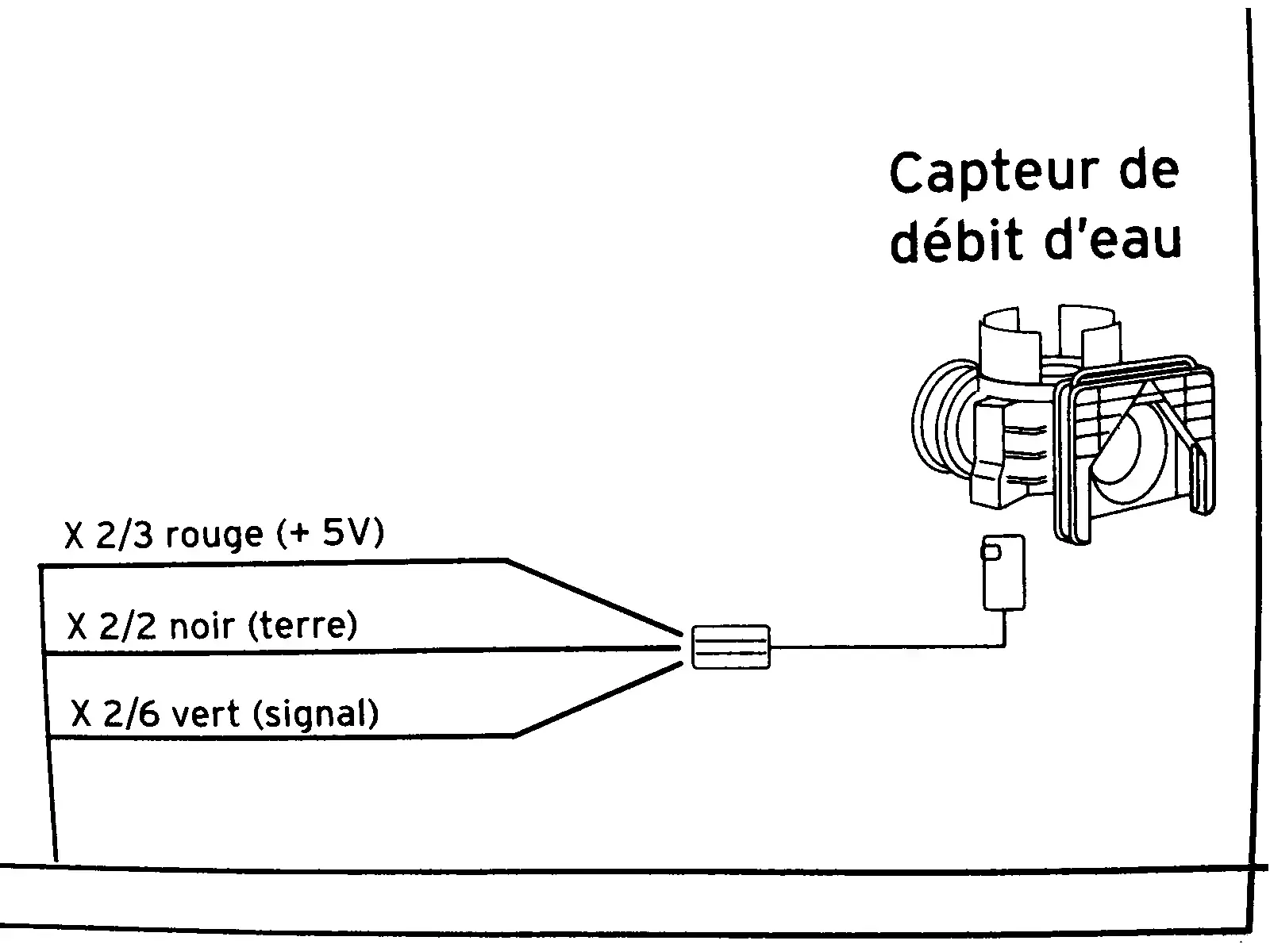
This diagram is from the service manual of a combi boiler. It’s a flow sensor which detects whether hot water is running, which is then used to trigger on-demand heat and switch a diverter to take radiators out of the loop.

In English, the diagram shows:

  • X ⅔ red wire (+5V)
  • X 2/2 black wire (ground)
  • X 2/6 green wire (signal)

I need to know what those fractions mean. I took the voltage measurements in this video:

I cannot necessarily trust the model in that video to have the same specs as mine. My voltmeter detected 4.68 V on the red input wire showing that the sensor is well fed. The green “signal” wire is supposed to be 0 V at rest and 2 V with water running (or I think the reverse of that is used in some models). In my case the green wire is ~1.33 V at rest and ~0.66 V when water is running. I need to know if these readings are normal as I troubleshoot this problem.

update


As the responders point out, the strings in the diagram represent labels for where the wires land on the motherboard. The underlying problem was also solved with the help of someone in a cross-posted thread.

top 2 comments
sorted by: hot top controversial new old
[–] ArcaneGadget 2 points 1 month ago* (last edited 1 month ago)

I'm 90% sure those fractions are connector and pin assignments.

X2/3 means connector X2 pin number 3

That's how it normally works.

Be sure to check that the ground connection has good continuity / low resistance. Bad grounds can do all kinds of funky stuff.

[–] [email protected] 2 points 1 month ago

No idea on the fractions however what does the sensor wire connect to? If you know the specifications of the next component you could maybe tell if the 1.33v or 0.66 is enough to trigger it. But I would guess it’s functioning probably given that it changes so dramatically, although I wonder why it’s not getting the full 5v?