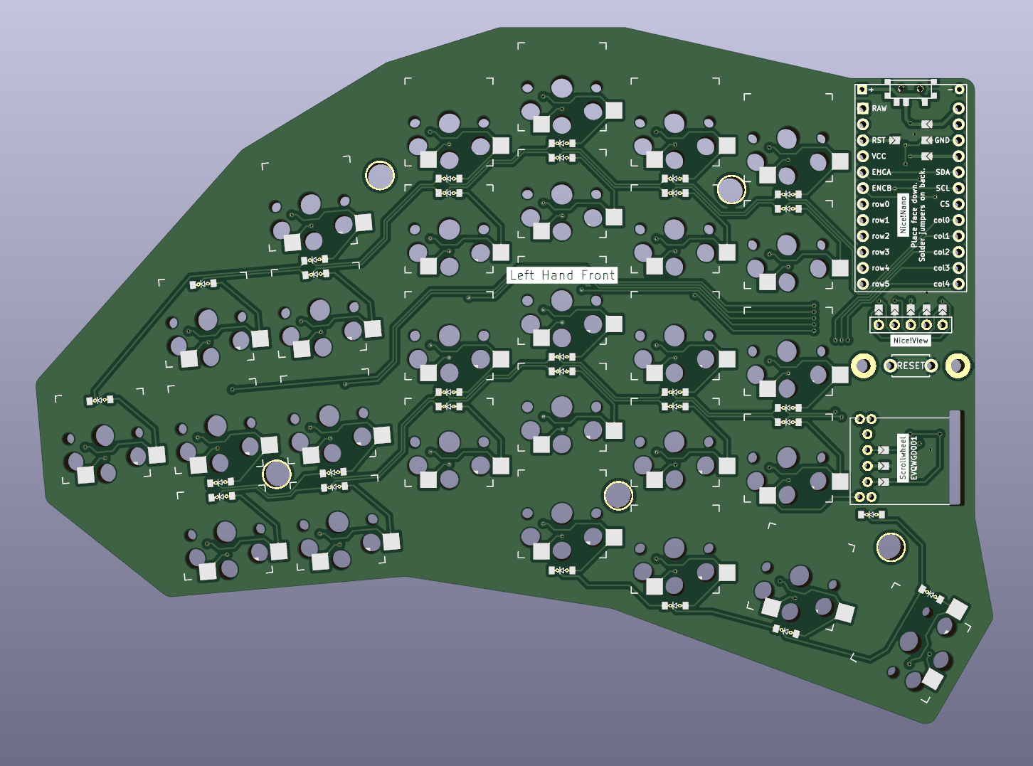
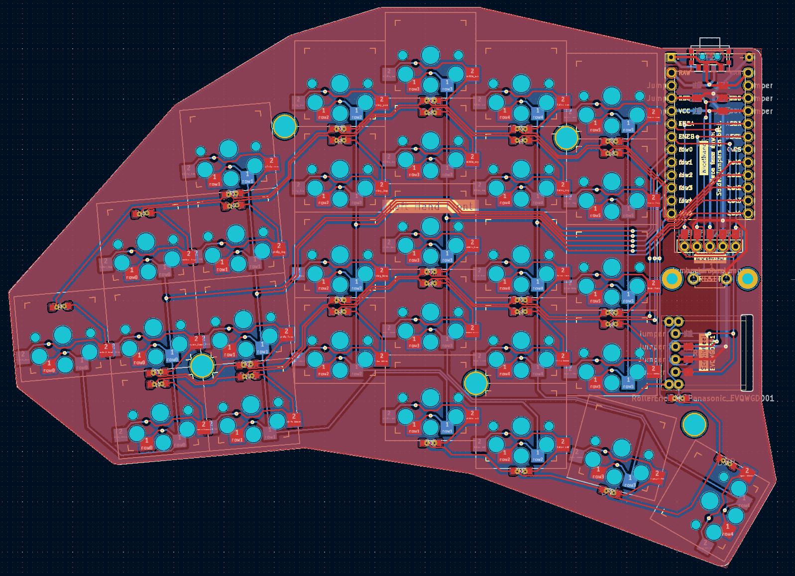
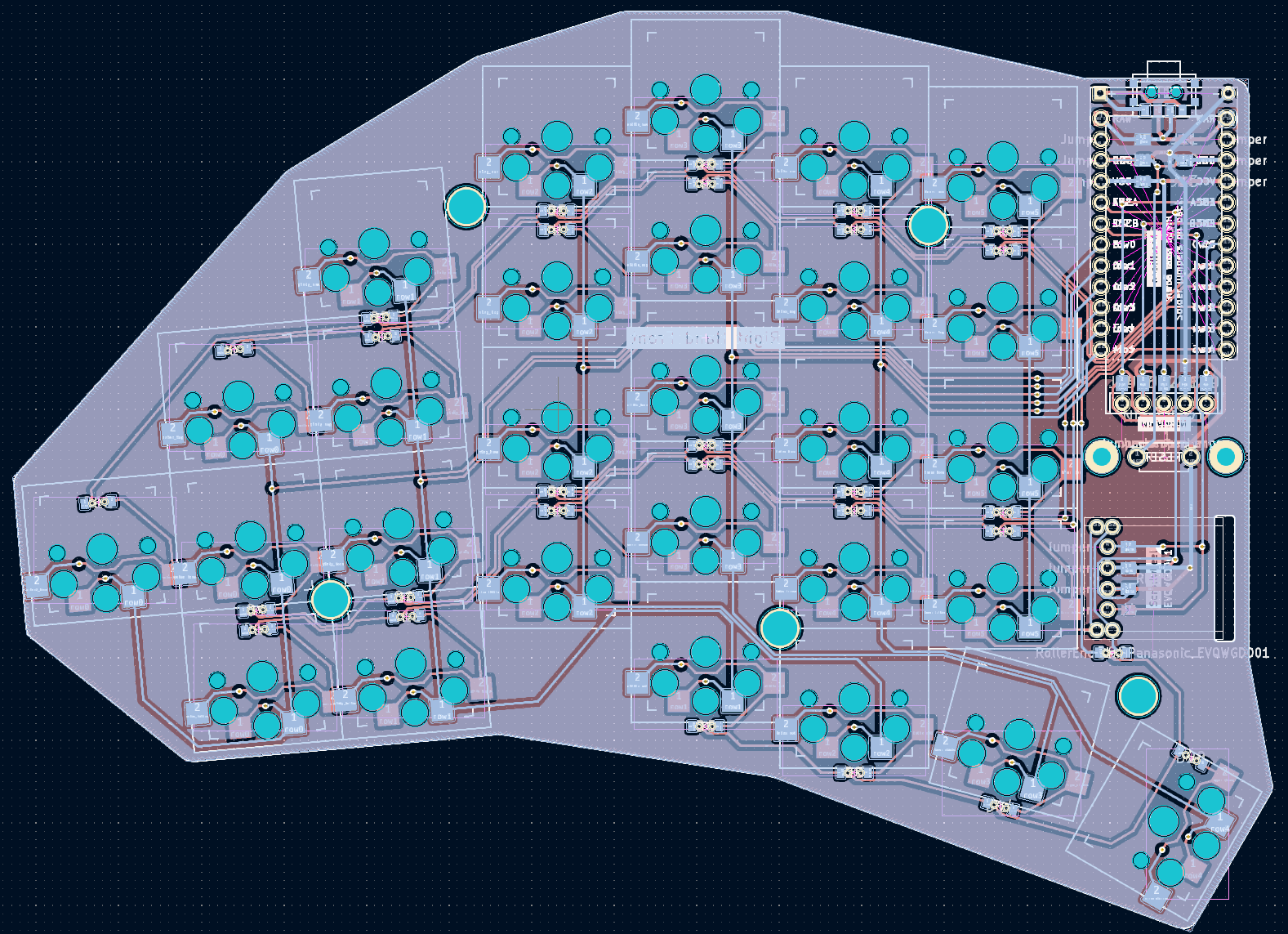
I'll give things a look over. First thought, you ground poured, but didn't link any of it together with vias. That would be helpful in ensuring good ground return paths.
ErgoMechKeyboards
Ergonomic, split and other weird keyboards
Rules
Keep it ergo
Posts must be of/about keyboards that have a clear delineation between the left and right halves of the keyboard, column stagger, or both. This includes one-handed (one half doesn't exist, what clearer delineation is that!?)
i.e. no regular non-split¹ row-stagger and no non-split¹ ortholinear²
¹ split meaning a separation of the halves, whether fixed in place or entirely separate, both are fine.
² ortholinear meaning keys layed out in a grid
No Spam
No excessive posting/"shilling" for commercial purposes. Vendors are permitted to promote their products/services but keep it to a minimum and use the [vendor] flair. Posts that appear to be marketing without being transparent about it will be removed.
No Buy/Sell/Trade
This subreddit is not a marketplace, please post on r/mechmarket or other relevant marketplace.
Some useful links
- EMK wiki
- Split keyboard compare tool
- Compare keycap profiles Looking for another set of keycaps - check this site to compare the different keycap profiles https://www.keycaps.info/
- Keymap database A database with all kinds of keymap layouts - some of them fits ergo keyboards - get inspired https://keymapdb.com/
Yeah just some vias for return to ground; everything looks reasonably fine from a quick overview. You have space, and cross talk really isn't a concern, but more padding between signal traces could be helpful in some of the closer areas. Though all of that is minimal in concern.
I just kept the default value (I think its 0.2mm) between traces. I could probably double it at some points where multiple traces are bundled though. Thanks for the hint!
thanks for the imput. Do you mean I should just place some random vias to connect both sides of the ground plane? To be honest, I dont understand exactly what this ground plane is used for since none of the traces actually connect to it. Is it merely for shielding against signal noise?
I'm no electrical engineer. But I was informed that having the return to ground close to all data connections is a good thing from a EMI and signaling perspective. I often put ground vias near all my rows and column pads.
Are you in the Absolem Discord? They can probably help you confirm everything looking right.
good idea!
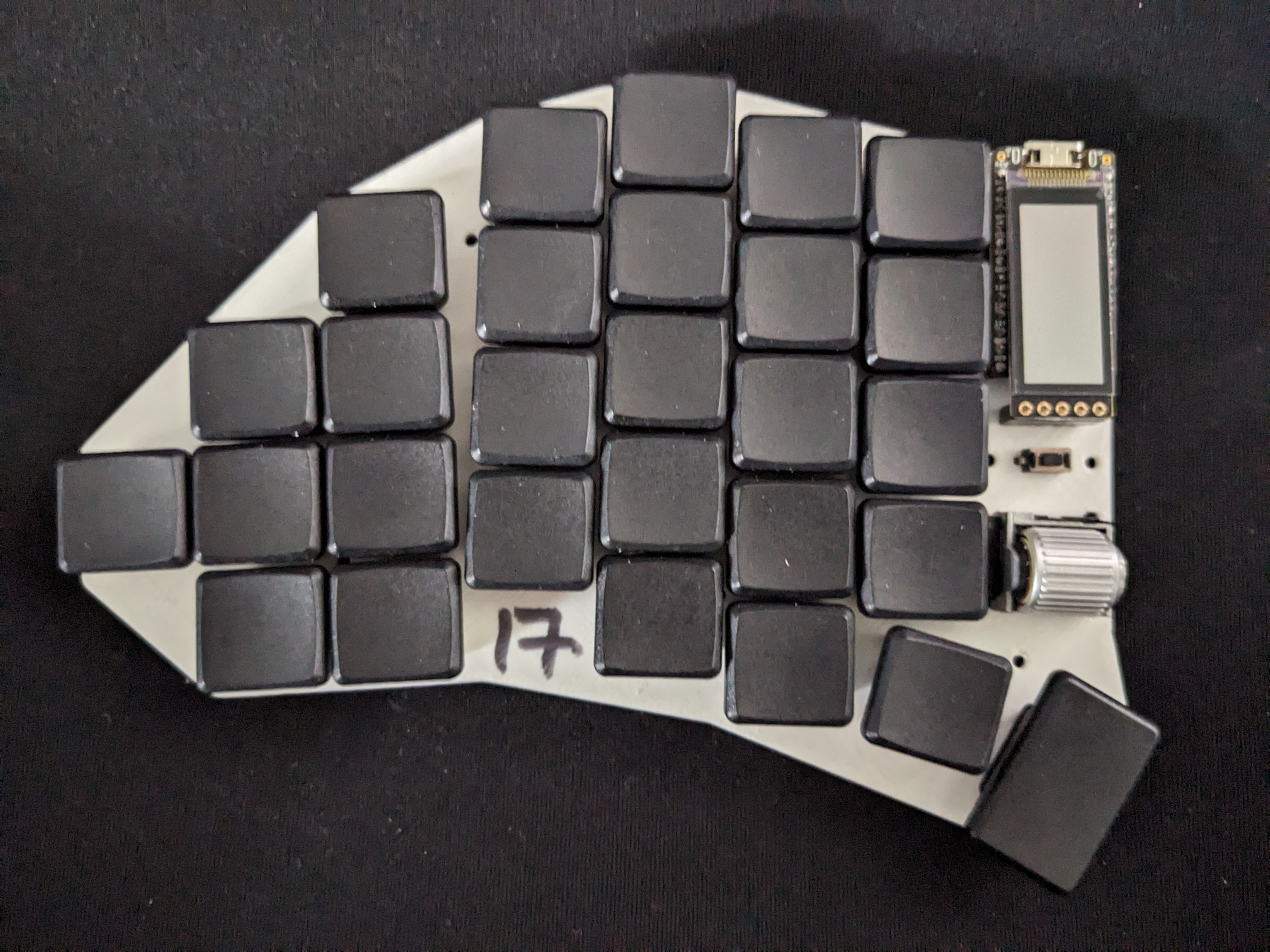
Interesting design. Wish I could produce something that works for me.
I'm not a designer or engineer.
Only error I noticed is the "." at the end of your url
https://github.com/dnlbauer/splitkeyboard.<- leads to 404.
fixed the domain. thanks for pointing that out!
If you are interested in the design process, I can highly recommend the tutorial series by FlatFootFox here. It was a great resource for me to get started. https://flatfootfox.com/ergogen-introduction/
Hi, this looks interesting to me. I will happily take a look at this for you. Do you have the KiCad schematic file as well (with file extension ".kicad_sch")?
Hey, unfortunately erdogen, which I used to generate the starting point for the pcb does not generate a schematic file. It only generates the PCB and ratsnest for the footprints. So I dont have one. I think I could create one though. Mind telling me what this is used for and why one should have one?
It's mostly useful for reference. If I open up both the PCB file and the schematic file, clicking on one element of the PCB will highlight the same item in the schematic, so I can double-check connections.


