ErgoMechKeyboards
Ergonomic, split and other weird keyboards
Rules
Keep it ergo
Posts must be of/about keyboards that have a clear delineation between the left and right halves of the keyboard, column stagger, or both. This includes one-handed (one half doesn't exist, what clearer delineation is that!?)
i.e. no regular non-split¹ row-stagger and no non-split¹ ortholinear²
¹ split meaning a separation of the halves, whether fixed in place or entirely separate, both are fine.
² ortholinear meaning keys layed out in a grid
No Spam
No excessive posting/"shilling" for commercial purposes. Vendors are permitted to promote their products/services but keep it to a minimum and use the [vendor] flair. Posts that appear to be marketing without being transparent about it will be removed.
No Buy/Sell/Trade
This subreddit is not a marketplace, please post on r/mechmarket or other relevant marketplace.
Some useful links
- EMK wiki
- Split keyboard compare tool
- Compare keycap profiles Looking for another set of keycaps - check this site to compare the different keycap profiles https://www.keycaps.info/
- Keymap database A database with all kinds of keymap layouts - some of them fits ergo keyboards - get inspired https://keymapdb.com/
view the rest of the comments

Hey! Glad my project inspired you! If you want more pins on the WS touch module, you can use an i2c expander board. It uses only two wires for SDA and SCL (plus two for power) and gives you a bunch of digital pins. And there is one i2c port available on the board (I’m using it to connect an IMU in my other project.
For mounting the board I clamped it between a ring and some tabs holding the module down (I’ll link to photos soon) I also looked into QMK integration and it seems it would be doable, but would require some extra coding to make the touch interface talk to QMK. Then you would still need custom firmware to animate the screen.
Also for the screen, I recommend looking into LVGL. It’s a library that allows you to build reactive interfaces easily. It even had a UI builder app where you can drag and drop your elements to make your interface. It’s. Bit buggy but the best I found.
Lastly, my idea for my trackpad project right now is to actually use it separately from the keyboard entirely and have a usb splitter hidden in the case to connect both.
This is my CyberLevel project that uses the same module. You can see the way I mounted the screen my catching the edges of the screen and clamping it down to the case. In the case are small cutouts that allows the PCB to lean on without touching components.
https://imgur.com/a/u1HeqRa
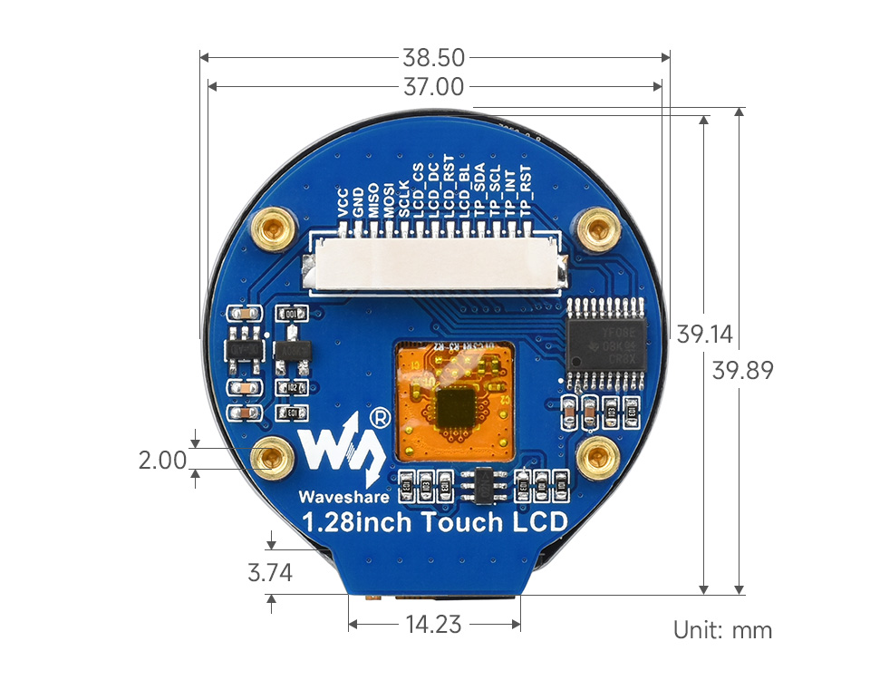
It's not exactly the same module, but similar. Pretty much the same thing but without the RP2040 MCU on board. I picked it up mainly because of the M2 screw posts. Too bad it doesn't use regular goldpin headers like the one without touch... It would make things so much simpler. I'd really like to avoid having a mess of tangled wires, but it would require me to find a connector that plugs directly downwards. Just like goldpin does, only twice as tight.
FYI, the non-touch version doesn’t use standard pin sizes. They’re much smaller (I got one and was super disappointed). For the connector. Right now I have a tangle of wires but I’m planning on cutting them and solder them. The benefit of the connector is that it makes it super easy to remove the module. To keep wires clean, you can braid them, or keep them together with some heat shrink.
Ugh. That kinda sucks. Although now that I actually took a look, it's written in the specs. It's 1.27mm goldpin. Less popular, but still pretty simple to get around. I think I might actually be able to convert my module from JST to 1.27mm goldpin with something like this. The difference between 1.25mm and 1.27mm across 13 pins should not be big enough to make a difference. I hope...