this post was submitted on 15 Nov 2024
109 points (99.1% liked)
Electronics
2077 readers
1 users here now
Projects, pictures, industry discussions and news about electronic engineering & component-level electronic circuits.
Rules
1: Be nice.
2: Be on-topic (eg: Electronic, not electrical).
3: No commercial stuff, buying, selling or valuations.
4: No circuit design or repair, tools or component questions.
5: No excessively promoting your own sites, social media, videos etc.
Ask questions in https://discuss.tchncs.de/c/askelectronics
founded 2 years ago
MODERATORS
you are viewing a single comment's thread
view the rest of the comments
view the rest of the comments

Looks great! It looks like you might have watched my video :)
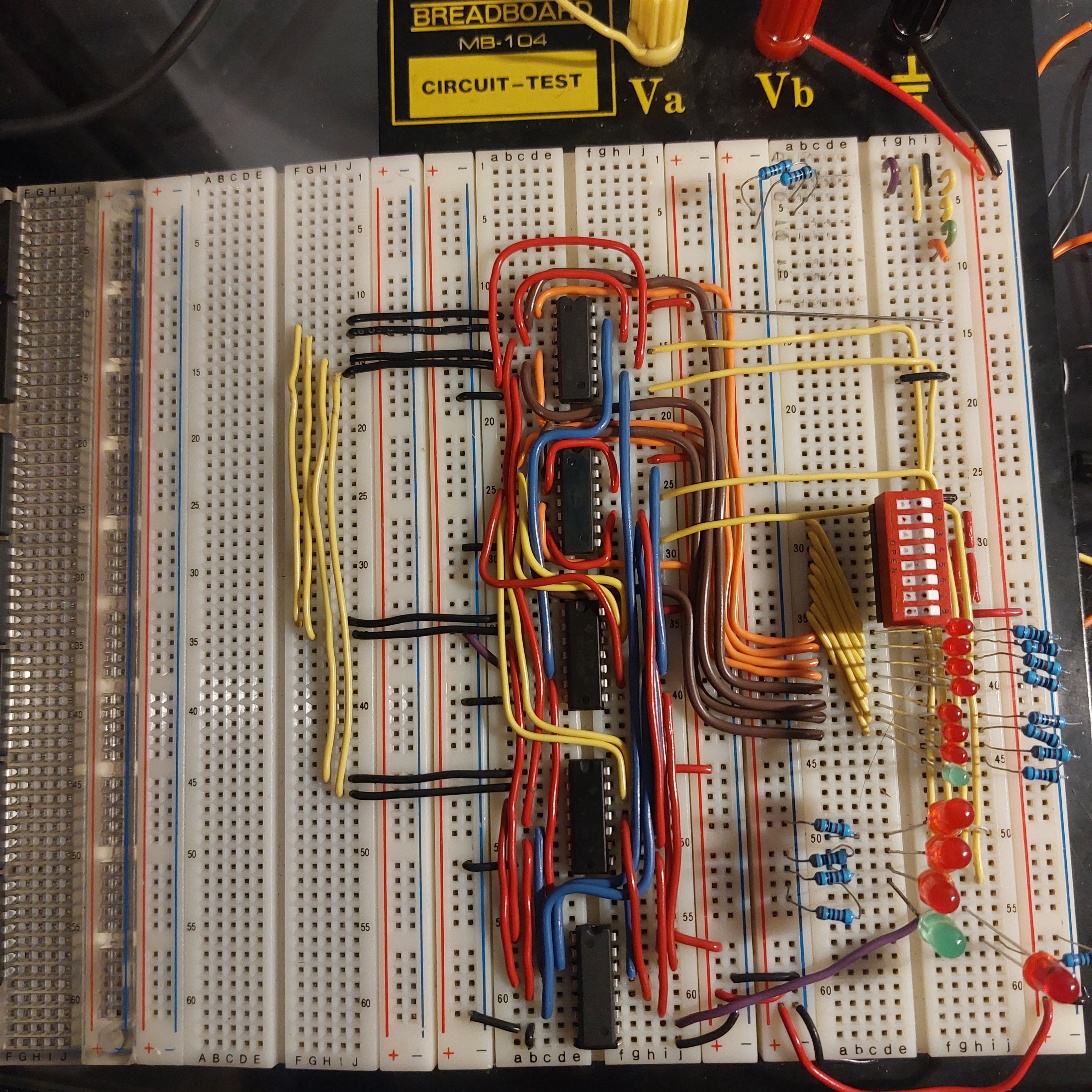
Not knowing the schematic, is there a specific reason you have those yellow traces broken out to the left? Looks like you could have done them single wires.
De obfuscation and pin hole crowding. I was struggling to fit the wires and see my pin holes so I moved the 4 wires that would have been on top of eachother over to make room for the rest of the wiring.
Ah. My only suggestion then would be to reduce the likelihood of errors by just combining each pair of black wires with its yellow wire, so it's one continuous wire. It could still follow the same route and keep your main section less crowded, but there'd be fewer connections to worry about. And you could hold them there with little jumpers like you did in the top right section.
Thank you.