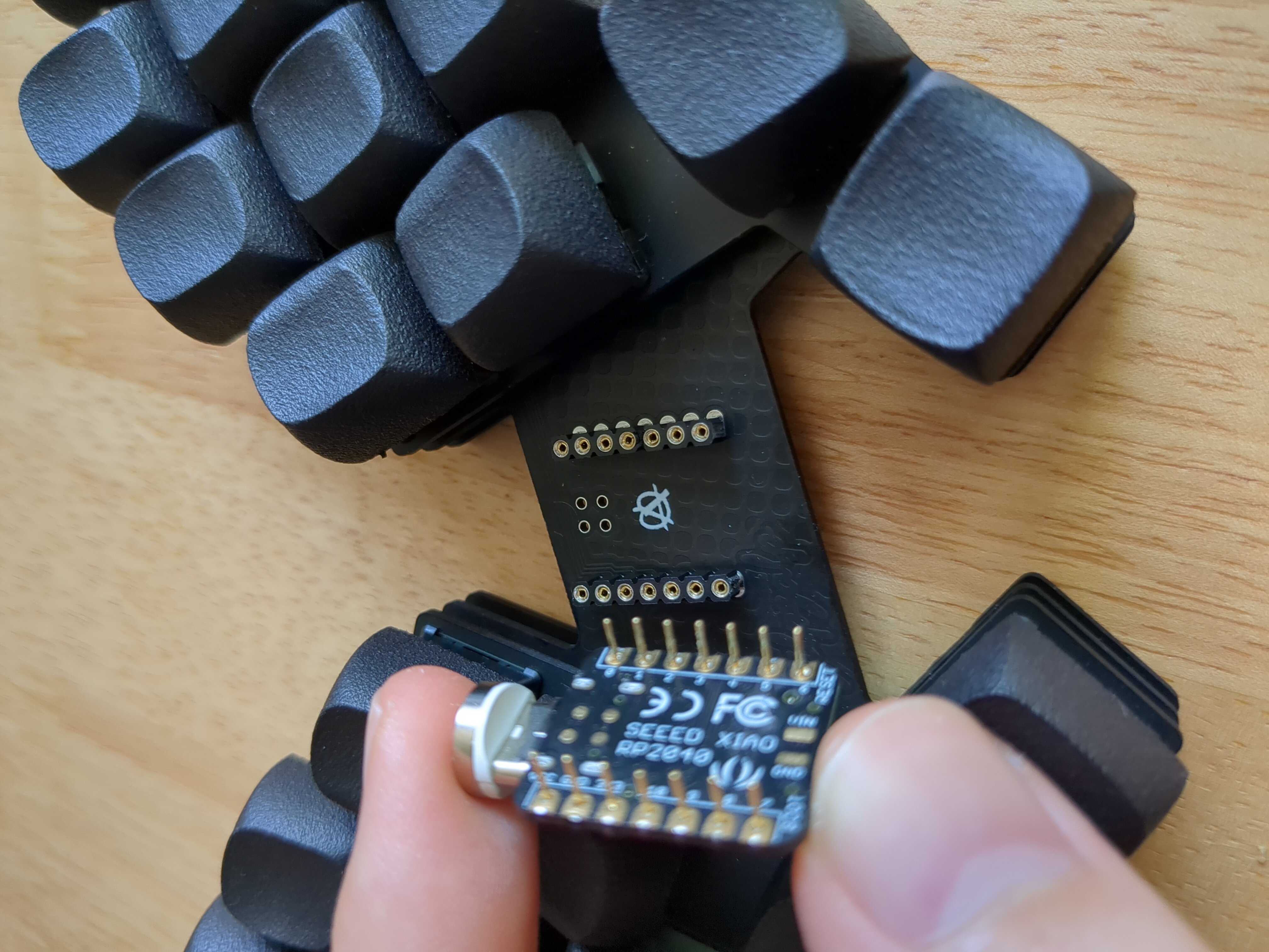
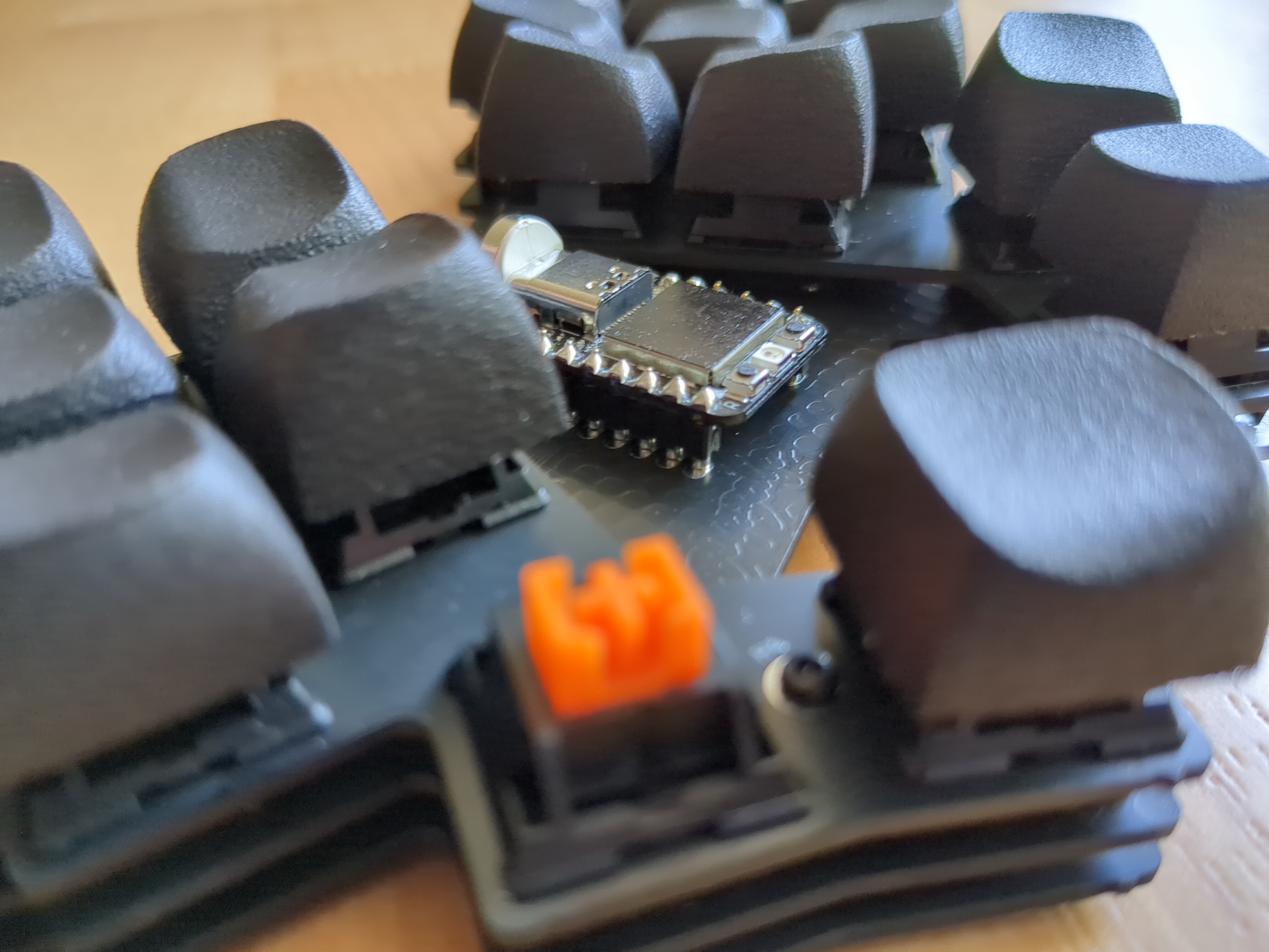
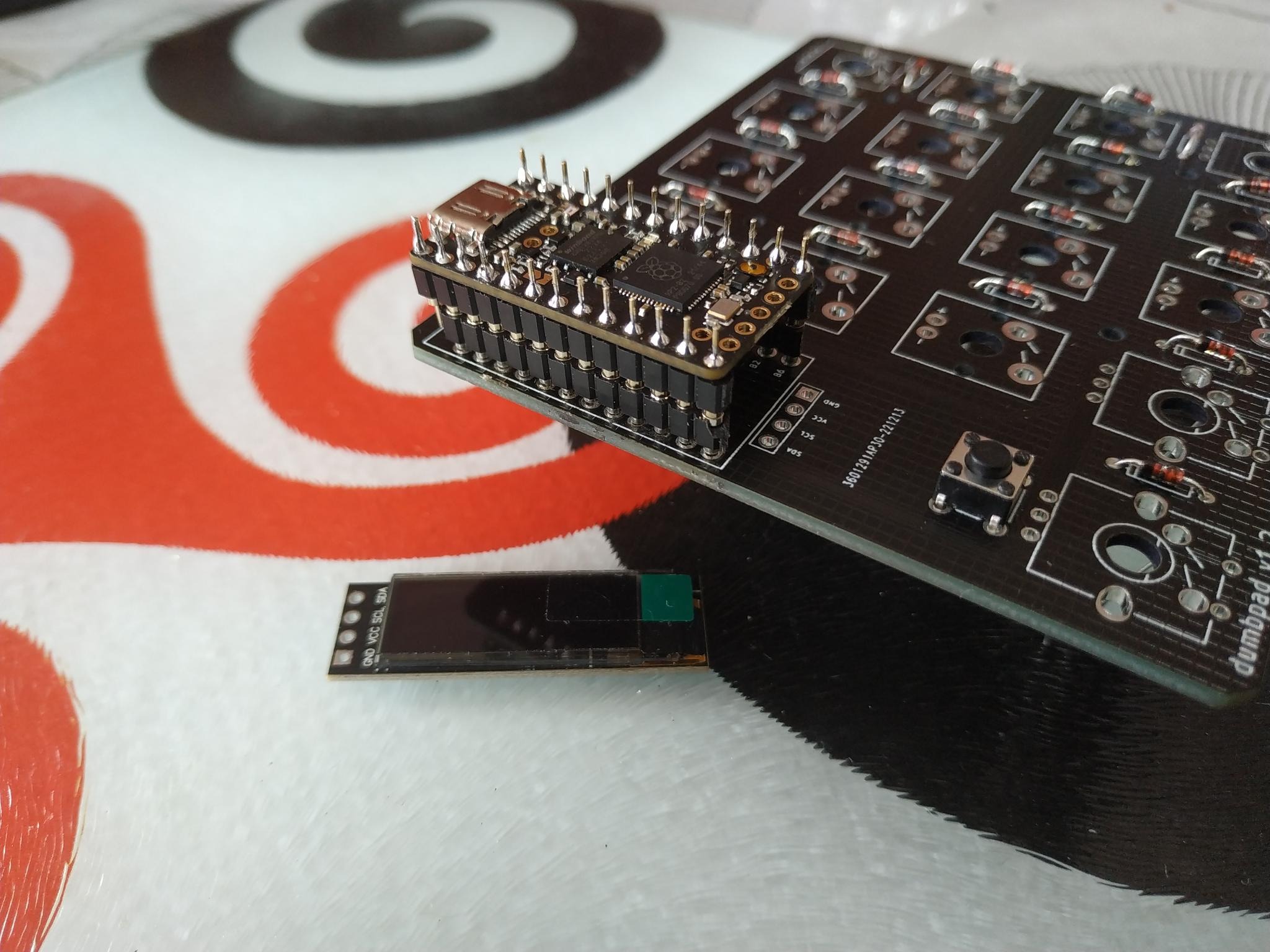
Wait, you socketed the controller and then put those sockets into more sockets?
ErgoMechKeyboards
Ergonomic, split and other weird keyboards
Rules
Keep it ergo
Posts must be of/about keyboards that have a clear delineation between the left and right halves of the keyboard, column stagger, or both. This includes one-handed (one half doesn't exist, what clearer delineation is that!?)
i.e. no regular non-split¹ row-stagger and no non-split¹ ortholinear²
¹ split meaning a separation of the halves, whether fixed in place or entirely separate, both are fine.
² ortholinear meaning keys layed out in a grid
No Spam
No excessive posting/"shilling" for commercial purposes. Vendors are permitted to promote their products/services but keep it to a minimum and use the [vendor] flair. Posts that appear to be marketing without being transparent about it will be removed.
No Buy/Sell/Trade
This subreddit is not a marketplace, please post on r/mechmarket or other relevant marketplace.
Some useful links
- EMK wiki
- Split keyboard compare tool
- Compare keycap profiles Looking for another set of keycaps - check this site to compare the different keycap profiles https://www.keycaps.info/
- Keymap database A database with all kinds of keymap layouts - some of them fits ergo keyboards - get inspired https://keymapdb.com/
I've soldered the female headers on the board:

The the male on the controler :

I see. So you have two sets of sockets: soldered ones (those on your controller) and hot-swappable ones (those on your board), and you've stacked them. It will probably work fine, but the usual approach is using only one of these.
Example for the hot-swappable ones:


Thanks ! I understand what I did wrong. I do not have the motivation to remove the header from the controller and put them in a proper way. I will keep it as is — as the result from my first attempt to solder my keyboard!
Now I have to find a way to stack three layer for the screen!
Just happy little accidents! :)
I am a bit confused by your photo and the other comment.
Usually you installed female headers on the board and male pins on the controller.
Most keyboard designs also ask for the controller to be installed with the components facing down and not up like in your image.
So make sure to double check the correct direction for your keyboard before turning it on.
For the display you can use the same female headers and then just make the male pins that you solder to the display longer.
I recommend watching this stream of a lily58 keyboard build. It’s done by the creator of the nice nano.
He shows how to properly solder controllers, sockets, diodes and so on. o
Thanks for taking your time and your remarks !
The dumbpad requires the controller to be facing up. The PCB helps because the pinout is printed on the board, and I’ve double checked the "GND" pins with the square hole on the controller. I’ve already plugged the controller and test the reset button: everything worked fine !
Thanks for your video ! I will see if I can keep some diode legs as male pin the screen.
