this post was submitted on 12 Sep 2024
18 points (95.0% liked)

Ask Electronics

3173 readers
1 users here now

For questions about component-level electronic circuits, tools and equipment.

Rules

1: Be nice.

2: Be on-topic (eg: Electronic, not electrical).

3: No commercial stuff, buying, selling or valuations.

4: Be safe.


founded 1 year ago
MODERATORS
 

I've been messing around with circuits my entire life but this design was time sensitive and I've never done my own PCB designs before, so I hired someone to put this together. After getting some test boards, when I plug them in the charger chip gets very hot and smells like burning....

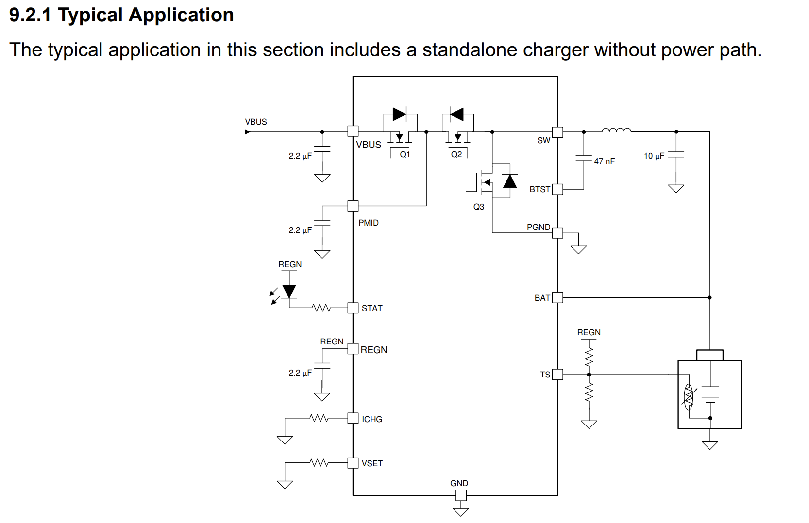
Circuit is just a simple li-ion usb charger and a switch. I've gone through the datasheet for the bq25302 more times than I can count and I'm missing something obvious here. Using it just for delivering power seems to work fine, the problem is only when charging.

I do see R6 + R7 off TS don't have the recommended 10k values, but I don't feel like that would cause what I'm seeing. This is being connected to a 21700 lipo.

Someone mind lending me their eyes please?

bq25302 datasheet - https://www.ti.com/lit/ds/symlink/bq25302.pdf

top 8 comments
sorted by: hot top controversial new old
[–] [email protected] 4 points 2 months ago (1 children)

I could be wrong, but I did finish a degree in EE even if I just do software now. But here's my quick take on it.

Probably because you're driving voltage on STAT from REGN.

STAT should have a current limiting resistor on it, go through your led, then ground.

REGN should have a 2.2uf cap between the pin and ground according to the datasheet.

[–] [email protected] 2 points 2 months ago

STAT should have a current limiting resistor on it, go through your led, then ground.

That would make sense, but page 21 of the datasheet with a typical application shows it going to REGN.

If it's missing the cap on REGN though, that would probably fuck this all up? I must admit I'm not good at understanding when/where caps are applied.

[–] [email protected] 3 points 2 months ago (1 children)

There should be a capacitor between REGN and ground and BAT and ground.

[–] [email protected] 1 points 2 months ago (1 children)

Oooh, thanks.

Stupid schematic question for a second, when looking at this:

If the "REGN" above the LED there is just referring to the REGN pin right below, why doesn't the line just go back down to the pin? Is this just a style thing, or does it mean something functionally different?

[–] [email protected] 3 points 2 months ago (1 children)

It means the same thing. I would have just drawn a line since they are right next to each other.

[–] [email protected] 1 points 2 months ago
[–] [email protected] 1 points 2 months ago (1 children)

If you don’t mind me asking: what is this for? Is it a hobby? I have no idea if any of this, just somehow came across your post

[–] [email protected] 1 points 2 months ago

Long term hobby that I'm trying to now turn into a small business / online store.